1OM-1064-002.pdf - 第53页
3.5 Priority Sorting Function By entering a numeral code “0 to 9” in the “C” data field in the placement (P) data, the component placement sequence is changed and number of nozzle change times is reduced to avoid deterio…
3. Functions
9910-001 1-22 Tg0246-PM-OP
3.3 Equivalent Repetitive Pattern Function
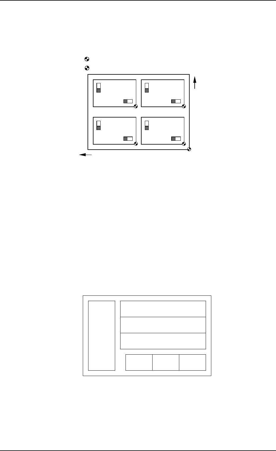
Pattern program data for unit P.C.B.’s (same repetitive patterns) can easily be
created through a combination of coordinate data of repetitive placement pat-
terns and each placement pattern origin.
The center of mark is P.C.B. positioning reference.
The center of mark is Pattern Origin.
Fig. 1.3
Refer to “2.6.3 PLACEMENT DATA (O) Display [Repetitive Placement
Data] of Section 2 in Volume 2” for details.
3.4 Function for Multi-Model Repetitive Patterns
(Application for Un)
By preparing several placement data in one pattern program, it becomes
possible to easily create a pattern program which covers the mixed patterns
for different models in equivalent P.C.B.’s.
A repetitive pattern can be set independently in each placement data.
Example: This function is used for such a P.C.B. as shown below.
Pattern A (3) Pattern A (1)Pattern A (2)
Pattern B (1)
Pattern B (2)
Pattern B (3)
Pattern C
Fig. 1.4
Refer to “3.2.5 Placement Data for Multi-Model Repetitive Patterns (Applica-
tion for Un) of Section 2 in Volume 2” for details.
Y Direction
X Direction

3.5 Priority Sorting Function
By entering a numeral code “0 to 9” in the “C” data field in the placement (P)
data, the component placement sequence is changed and number of nozzle change
times is reduced to avoid deterioration of productivity.
Refer to “3.2.6 Placement Data for Priority Sorting Function of Section 2 in
Volume 2” and “3.2.7 Priority Sorting Application for Multi-Model Repetitive
Patterns of Section 2 in Volume 2” for details.
3.6 Component Library
A set of data related to component placement is organized as a group of specific
component data (information) and managed as a data base in the form of a
component library.
As each component data is created and managed as a component library, it is
not necessary to create component data for each individual pattern programs,
greatly shortening the time for pattern program data creation and editing.
Refer to “COMPONENT LIBRARY” for details.
3.7 Automatic Feeder Axis Adjustment Function
The machine is provided with the recognition function which corrects the posi-
tional deviation of the picked component for accurate component placement.
By feeding the recognized amount of correction back to the pick-up position, the
pick-up position can be brought close to the specified one, realizing the stable
component picks.
Refer to “5.1 AUTOMATIC FEEDER AXIS ADJUSTMENT MODE Dis-
play of Section 3 ” for details.
3.8 Automatic Recovery Function (Reserved Data)
Compared with the normal operation mode in which the machine immediately
stops for component replenishment (priority) after a component shortage or
processing error is detected, this function makes the machine continue to
pick up components from another feeder without picking up components from
the feeder where the component shortage error has occurred. When all unit
PCBs are finished with some components missing, the machine stops in a
state which allows component supply. When pick-up operation is re-started
after the empty feeder is replaced with a full feeder, components are
placed on the component-missing areas on the processed PCBs. When a
component shortage error occurs in the automatic recovery mode, an error
message will prompt the operator to supply the components; but the machine
continues to pick up components from the other feeders and place them on
PCBs. When component shortage errors occur in a different feeder over a
short interval, the feeders can all be replenished collectively with
components to reduce loss time.
3. Functions
9910-001 1-23 Tg0246-PM-OP

3.9 Alternate Mode
• Carriage Alternate Function (Multi-Layer Tray Unit [Option])
The trays having the same type of components can be set on several stages
(pallets) in the magazines. Every time the machine gets empty of compo-
nents, it automatically selects another spare stage which stores the tray hav-
ing the same type of components, and the operation can be continued.
By providing several stages with a group of components used frequently
among the component types, an interval of component supply can be pro-
longed.
The order of the carriage alternate actions is based on the ascending order
(advancing from a smaller step No.) of the magazine step Nos.
Refer to “2.5.4 Tray Step Information (Option) of Section 2 in
Volume 2” for details.
• Magazine Alternate Function (Multi-Layer Tray Unit [Option])
Components of the types required for the production model must be set fully
for both upper and lower magazines. When the magazine alternate function
is activated, the machine performs the automatic operation with either one of
the upper and lower magazines being connected. The connected magazine is
automatically changed to the other one set automatically ready for use right
after the connected magazine gets empty of the components, making it pos-
sible for the machine to perform the operation continuously. That is, this
function makes it possible to supply components from the trays during opera-
tion, reducing downtime of the machine for component replenishment.
Refer to “4.5.4 Editing of Tray Operation Data (Option) of
Section 2 in Volume 2” for details.
• Various Feeder Alternate Functions
Tape Feeder
Vibratory Stick Feeder
Every time a component shortage error occurs at a feeder, the component
pick-up position is shifted automatically to another alternative one (specified
as the substitute), making it possible for the machine to perform the opera-
tion continuously.
This makes it possible for several feeders to be replaced collectively for
component replenishment.
3.10 One-Touch Jump Function
(Jump to Substitute AUTO OPN. MODE
<PLACEMENT> Display)
Automatic operation can be started only when the “AUTO OPN. MODE
<PLACEMENT>” display is active.
When a display other than the “AUTO OPN. MODE <PLACEMENT>” dis-
play or the “MAIN MENU” display is active and the machine stops during
automatic operation due to component shortage, etc., the “AUTO OPN. MODE
<PLACEMENT>” display can be opened temporarily to re-start the automatic
operation.
Refer to “1. One-Touch Jump Function (Jump to Substitute “AUTO OPN.
MODE <PLACEMENT>” Display) of Section 3 in Volume 5” for details.
9910-001 1-24
Tg0246-PM-OP
3. Functions