1OM-1064-002.pdf - 第92页
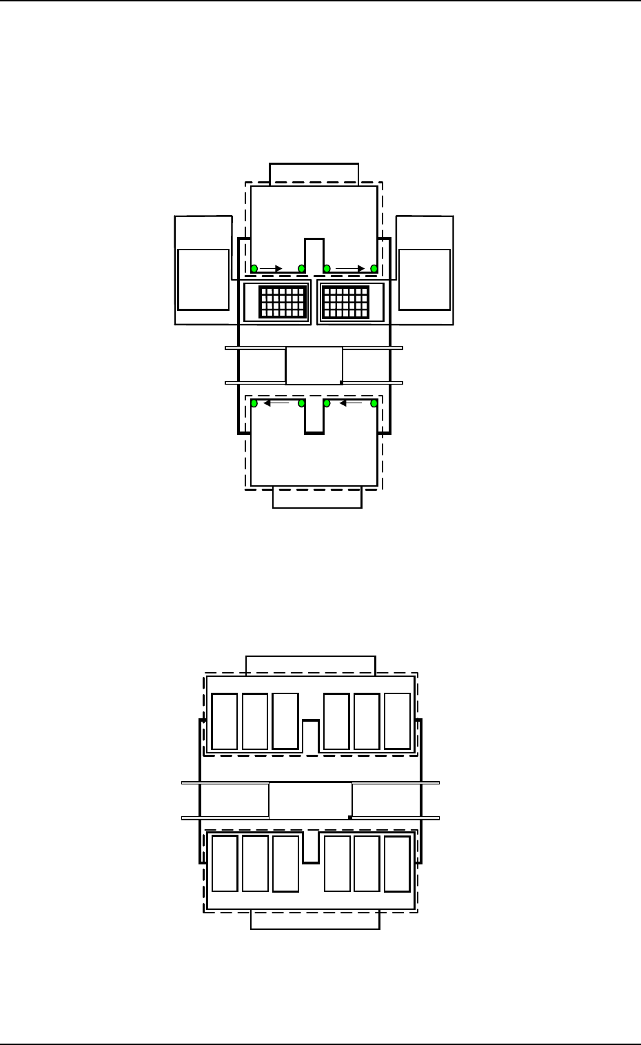
7. Construction of Feeder Carriages 0308-003 1-62 Tg0246-PM-OP 7.1 Feeder Installation on Carriages Adjoining Pitch for T ape Feeder Installation (1) Minimum Adjoining Pitch Based on Guide Feeder Note: Shown in Fig. 1.28…
Feeder Nos. (FDR NO)
The numerals show feeder Nos.
7. Construction of Feeder Carriages
0004-002 1-61 Tg0246-PM-OP
701 to799
801 to899
FDR No. 101 to 139
Beam A Side
Beam B Side
(Front Side of Machine)
Multi-Layer
Tray Feeder L
(Option)
601 to699301 to 399
401 to 499
501 to 599
219
…
201
239
…
221
…
139121119
…
101
Feeder
Base
#4
FDR No. 239
to 201
Feeder
Base
#3
Feeder
Base
#1
Feeder
Base
#2
TAPE
Multi-Layer
Tray Feeder R
(Option)
Feeder Base A
Feeder Base B
Fig. 1.27-1
Fig. 1.27-2
141
149
to
Feeder Base
#1
151
159
161
169
171
179
181
189
191
199
261
269
251
259
241
249
291
299
271
279
281
289
Beam A Side
FDR No. 141 to 199
FDR No. 299 to 241
Beam B Side
(Front Side of Machine)
Feeder Base
#2
Feeder Base
#4
Feeder Base #3
VIBRATORY STICK
Feeder Base A
Feeder Base B
to
to
to to
to
to to
to
to to
to
7. Construction of Feeder Carriages
0308-003 1-62 Tg0246-PM-OP
7.1 Feeder Installation on Carriages
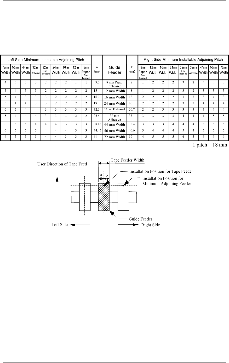
Adjoining Pitch for Tape Feeder Installation
(1) Minimum Adjoining Pitch Based on Guide Feeder
Note: Shown in Fig. 1.28 is a view based on the direction in which the feed-
ers are installed.
Table 1.9
Fig. 1.28
7. Construction of Feeder Carriages
0308-003 1-63 Tg0246-PM-OP
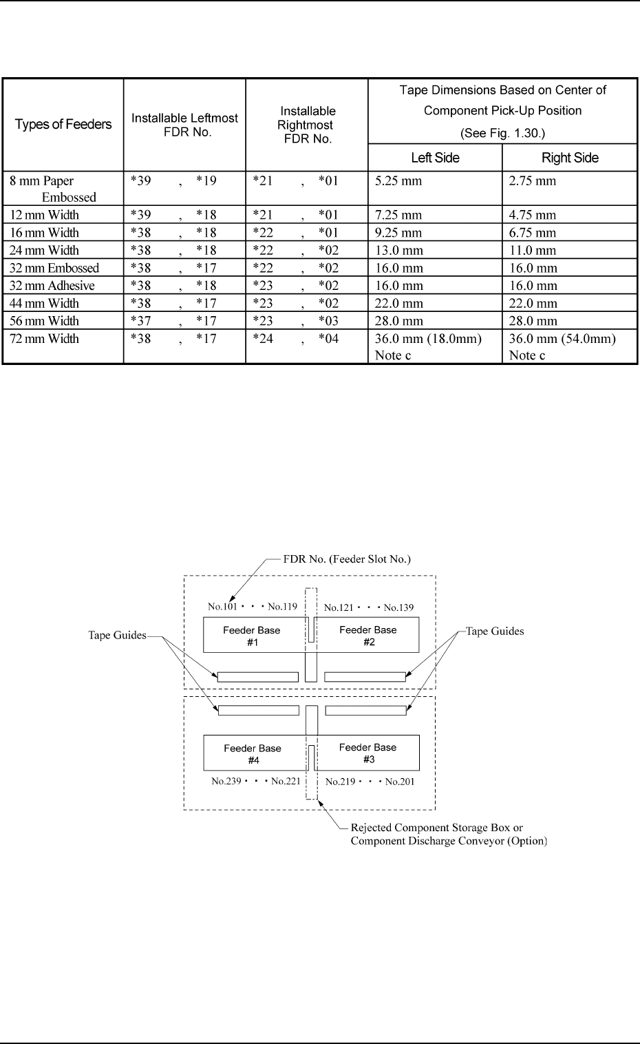
(2) Installable Feeder Slot Nos. at Both Feeder Base Ends
Note (a) Fig. 1.29 shows how the feeder bases are provided.
(b) Rejected component storage boxes or component discharge conveyors (op-
tion) can be mounted between Feeder Bases #1 and #2 and between Feeder
Bases #4 and #3.
(c) The dimensions in ( ) are those (tape width) based on the tape feeder instal-
lation position.
Table 1.10
Beam A Side
Beam B Side
(Front Side of Machine)
Fig. 1.29