1OM-1064-002.pdf - 第207页
6. RECOVERY OPN. TEACHING OPN. Display *1 FDR-NO This shows the feeder Nos. of the component data. The numbers in ( ) show the actual feeder slot Nos. The numbers in ( ) indicate the actual feeder slot Nos. where compone…
6. RECOVERY OPN. TEACHING OPN. Display
*5 *6
*4*3
*2
*1
*7
*8
*10
*9
*11
Fig. 3.20-1
[SCREEN (XX/XX)] key
Fig. 3.20-2
Fig. 3.20-3
9910-001 3-37 Tg0246-PM-OP
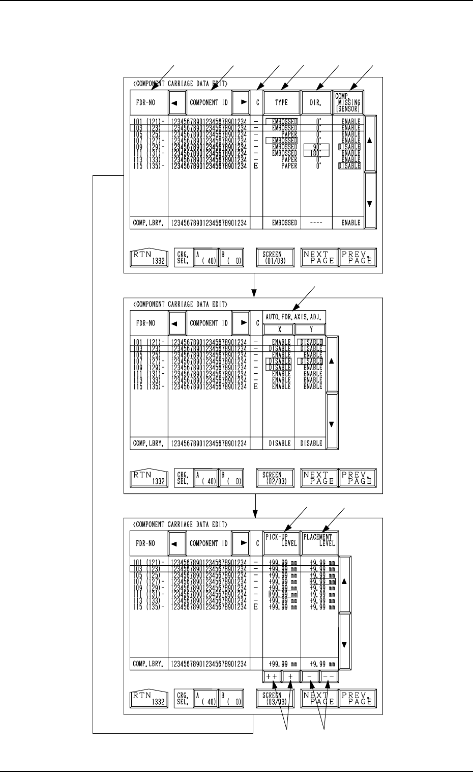
Every time the [SCREEN (XX/XX)] key is pressed, another display appears
on the screen.

6. RECOVERY OPN. TEACHING OPN. Display
*1 FDR-NO
This shows the feeder Nos. of the component data.
The numbers in ( ) show the actual feeder slot Nos.
The numbers in ( ) indicate the actual feeder slot Nos. where component
No. offset specified in the operation data is added.
In Fig. 3.16-1 (an example), “+20” is set as component No. offset.
Note: “- - -” appears in the “FDR-NO” field for the feeder slots where
feeders cannot be installed.
*2 COMPONENT ID
Component IDs are shown in the corresponding field.
*3 C
The control command is shown.
“-” : This command validates the steps as component data.
“S” : This command invalidates the steps specified as component data.
When component placement is specified for the invalid steps (FDR-
NO) in the placement data, the machine automatically omits the place-
ment operation for the step.
In this case, the background color of the “FDR” text field related to
the invalidated step turns red at the “PLACEMENT DATA” display,
indicating that the component placement is canceled.
“E” : This control command specifies the end of the component data.
(This step is handled as a valid step.)
“X” : This control command shows the end of component data and speci-
fies the step as an invalid step.
Remember this command as “X = S + E”.
*4 [TYPE] Key
Every time this key is pressed, the parameter at the line cursor position
changes in the order of “PAPER”, “EMBOSSED”, “ADHESIVE”, and
“BULK2”.
*5 [DIR.] Key
Every time this key is pressed, the parameter at the line cursor position
changes in the order of “0°”, “90°”, “180°”, and “270°”.
*6 [COMP. MISSING [SENSOR]] Key
When the vacuum is affected by the shape of components, etc., at compo-
nent picks and components cannot be detected normally by the vacuum
sensor, this key can be used to invalidate the component detection function
(component detection by vacuum sensor) at the “COMPONENT CAR-
RIAGE DATA EDIT” display.
“ENABLE” or “DISABLE” can be selected.
*7 AUTO. FDR. AXIS. ADJ. [X] and [Y] Keys
These keys can be used to cancel the automatic feeder axis adjustment
function for each individual components.
“DISABLE” is automatically set when the parameters set as the data for
automatic feeder axis adjustment at the “COMPONENT CARRIAGE
DATA EDIT” display exceed the limit for correction during pick-up posi-
tion correction.
9910-001 3-38 Tg0246-PM-OP

6. RECOVERY OPN. TEACHING OPN. Display
*8 [PICK-UP LEVEL] Key
When a fine adjustment of the pick-up level is required before and after
the level is changed and a slight difference is found in component thick-
ness, this key can be used to change the data for stable component picks.
Pressing this key makes it possible to change the numerical values.
*9 [PLACEMENT LEVEL] Key
When there is a slight difference between the original component thick-
ness (unchanged thickness) and the changed one, this key can be used to
change the data for stable component placement.
Pressing this key makes it possible to change the numerical values.
*10 [++] and [+] Keys
These keys can be used to increase the values in the “PICK-UP LEVEL”
or the "PLACEMENT LEVEL" data field.
[++] Key: Press this key to increase the selected value in the incre-
ments of 0.1 mm.
[+] Key : Press this key to increase the selected value in the incre-
ments of 0.01 mm.
*11 [-] and [- -] Keys
These keys can be used to decrease the values in the “PICK-UP LEVEL”
or the “PLACEMENT LEVEL” data field.
[- -] Key : Press this key to decrease the selected value in the incre-
ments of 0.1 mm.
[-] Key : Press this key to decrease the selected value in the incre-
ments of 0.01 mm.
• When the parameters (direction, type, component detection, automatic feeder
axis adjustment, pick-up level, and placement level) are different from those
defined in the component library data, the background color of the perti-
nent text fields turns red.
“-” appears beside the feeder Nos. (FDR-NO).
• The feeder slot Nos. (FDR-NO) can be selected only within the same
(shared) carriage.
To move to another carriage, select the [A (40)] or the [B (0)] key.
Operation Procedure
(1) Move the line cursor to the feeder slot No. (FDR-NO) where components
different from those (the components having the corresponding IDs) de-
fined in the component library data are supplied.
(2) Press the [TYPE], the [DIR.], the [COMP. MISSING [SENSOR]], the
[X] and [Y] of “AUTO. FDR. AXIS ADJ.”, the [PICK-UP LEVEL], or
the [PLACEMENT LEVEL] key and edit each corresponding parameter.
(3) When the [RTN] key is pressed, the following display appears on the
screen.
9910-001 3-39 Tg0246-PM-OP