1OM-1064-002.pdf - 第176页
3. AUTO OPN SUB-MENU Display Fig. 3.2-1 Operation Display for Side B Fig. 3.2-2 Operation Display for Side A Operation Keys *1 [P ASS/PLACE CHANGE] Key This key is used to change the placement mode (ON/OFF of V acuum Pum…
2. AUTO OPN MODE (PLACEMENT) Display
0103-001 3-6-1 Tg0246-PM-OP
•
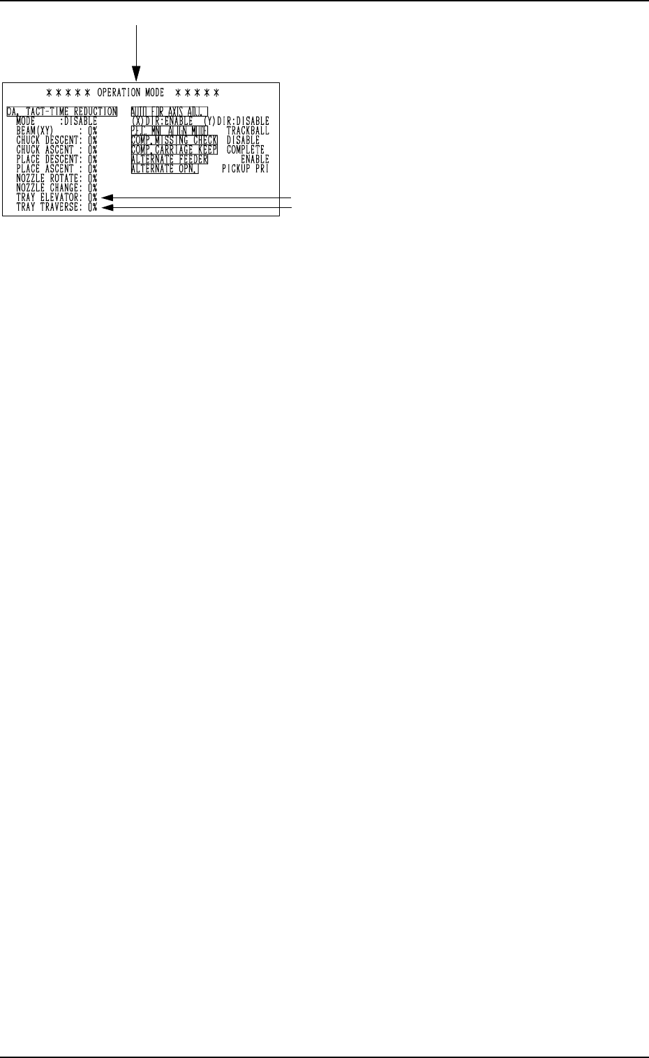
OPERATION MODE
Parameters set as operation mode are dis-
played.
Note: The -marked items are optional.
[SCREENS] Key
3. AUTO OPN SUB-MENU Display
Fig. 3.2-1 Operation Display for Side B
Fig. 3.2-2 Operation Display for Side A
Operation Keys
*1 [PASS/PLACE CHANGE] Key
This key is used to change the placement mode (ON/OFF of Vacuum
Pump).
Note: When the machine is set in the “STOP” mode, this key can be
selected.
*6
*5
*9
*8
*7
*4
*2
*3 *5 *4
*10
*11
*12
*13
*14
0103-003 3-7 Tg0246-PM-OP
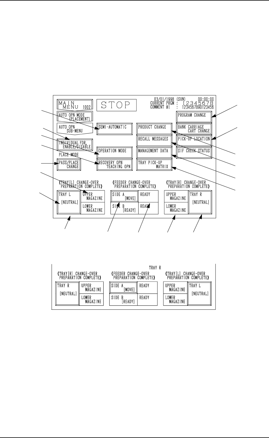
3. AUTO OPN SUB-MENU Display
When the [AUTO OPN SUB-MENU] key is pressed at the “AUTO OPN MODE
(PLACEMENT)” display, the following display appears on the screen.
Note: There is a slight difference in the operation displays between the front
side (Side B) and the rear side (Side A).
Operation and function keys required for automatic operation can
be selected at this display.
*16
*1
*15
3. AUTO OPN SUB-MENU Display
0004-002 3-8 Tg0246-PM-OP
*2 [SIDE A [MOVE]] or [SIDE B [READY]] Key/[SIDE B [MOVE]] or
[SIDE A [READY]] Key
These keys are used to inform the machine that a feeder on the feeder base
is set ready for replacement and component replenishment.
Note: Only the status is displayed on the operation-available side.
Press the [SIDE X [READY] key before performing the compo-
nent replenishment operation. “X” represents either “A” or “B”.
• When one of these keys is pressed with “NOT READY” in *3 and the
[MOVE] button is pressed after the key turns “ON” in blue, the opera-
tion available and opposite sides can be set ready for operation. (The
supply covers and the safety bars are locked and the machine starts run-
ning.)
• When one of these keys is pressed with “READY” in *3 and the [MOVE]
button is pressed after the key turns “ON” in blue, the operation avail-
able and opposite sides can be set ready for component supply opera-
tion. (The X/Y beam moves to its standby position, the supply covers
and the safety bars are unlocked, and the machine is set ready for com-
ponent supply to the tape feeders.)
WARNING
The X/Y beam on the opposite side to the op-
eration available side starts moving.
It is dangerous! Confirm that there is no person
on the opposite side.
When the machine is operated by more than
one person, ensure good communication by giv-
ing loud verbal instructions.
*3 Mode: “READY”, “NOT READY”, or “RUN”
A mode appears, indicating whether or not the machine is set ready for
component supply operation or showing that the machine is in the process
of mode change (“READY” to “NOT READY” or vice versa).
READY : The machine is set ready for component supply opera-
tion. The component supply operation can be performed.
NOT READY : The machine is not set ready for component supply op-
eration.
The supply covers and the safety bars are unlocked, mak-
ing it possible to supply components to the tape feeders.
RUN : The machine is in the progress of mode change
(“READY” to “NOT READY” or vice versa).
The machine is performing a series of operations such
as X/Y movement to the stationary position, X/Y beam
power ON/OFF, and electromagnetic locks ON/OFF.