1OM-1064-002.pdf - 第75页
• P .E.C. Recognition Coordinates System The posture of the placed component matches the image on the recognition monitor . Special attention is required to the direction keys for the screen movement made when the manual…
Picked Component
Captured Image on
Recognition Monitor
Placed Component
View from Front Side
of Machine
View from Rear Side
of Machine
3
2
41
2
3
1
4
1
4
2
3
1
4
23
2
3
1
4
1
4
2
3
• The recognition system (back lighting, front lighting, or front lighting (BGA)
system) can automatically be selected according to the component library
data.
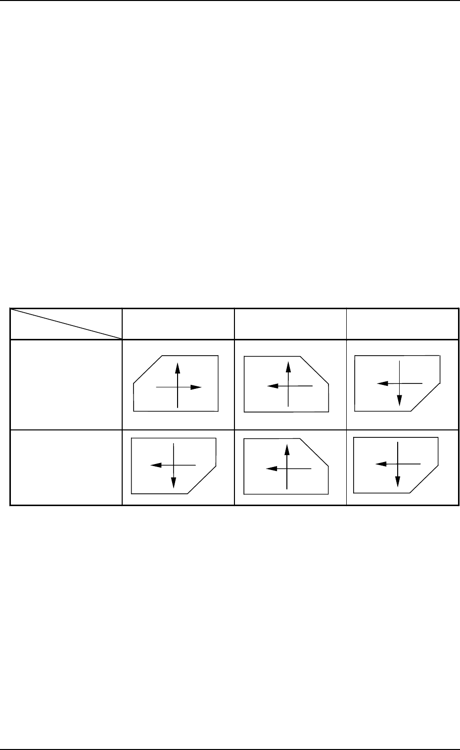
• Component Recognition Coordinates System
The image of the component (state of picked component based on the X/Y
beam movement) on the recognition monitor looks like those depicted be-
low.
View from Front Side of Machine:
The captured image of the picked component on the recognition
monitor is inverted horizontally, compared with the posture of the
picked component. Therefore, when the X/Y beam moves from left
to right, the image of the component moves from right to left on the
recognition monitor.
View from Rear Side of Machine:
The image of the component on the recognition monitor is inverted
vertically, compared with the posture of the picked component. There-
fore, when the X/Y beam advances from up (front side of machine)
to down (rear side of machine), the image of the component on the
recognition monitor moves up.
6. Outline of System Operation
9910-001 1-44 Tg0246-PM-OP
Table 1.6
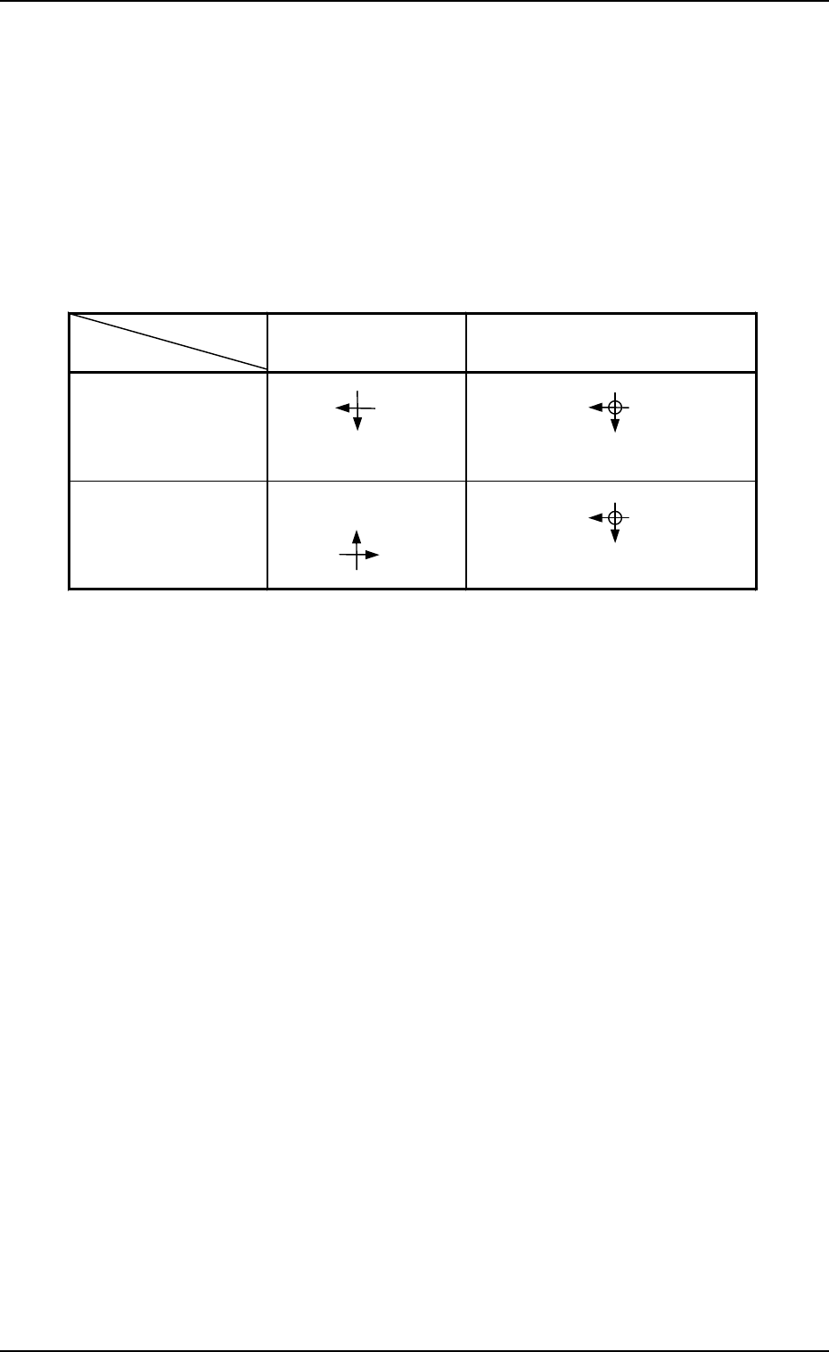
• P.E.C. Recognition Coordinates System
The posture of the placed component matches the image on the recognition
monitor.
Special attention is required to the direction keys for the screen movement
made when the manual axis operation is performed on the front side of the
machine because the CCD camera moves together with the X/Y beam.
The directions of the X/Y beam movement and the fiducial mark movement
on the recognition monitor are inverted (upside down, leftside right).
The directions are not inverted when the machine is operated on the beam A
side.
6. Outline of System Operation
9910-001 1-45 Tg0246-PM-OP
Direction of X/Y
Beam Movement
Direction of Mark Movement on
Recognition Monitor
Operation on Beam
A Side
Operation on Beam
B Side
X
Y
X
Y
X
Y
X
Y
6.2.3 Correction of Recognition
Theta (Angle) Correction
The picked component is adjusted to the angle (placement direction) of place-
ment specified in the pattern program by rotating the head.
At this time, the angular deviation (θ) detected through component recogni-
tion is also corrected.
Component Placement
(1) The X/Y beam moves.
The X/Y beam is moved to the coordinates (position on P.C.B.) specified
in the pattern program.
At this time, the measured positional deviation (X, Y) between the cen-
ters of the recognition camera and the component is corrected during the
X/Y beam movement.
(2) The placement Z correction is made.
The lowest limit in nozzle height is controlled based on the component
library data when components are placed.
(3) Vacuum turns off, air blows out from the nozzle, and components are
placed on the P.C.B.
Table 1.7
6. Outline of System Operation
0004-002 1-46 Tg0246-PM-OP
6.3 P.C.B. Transfer
The operation related to the P.C.B. transfer changes depending on the P.C.B.
transfer reference point, the P.C.B. positioning spot, and the P.C.B. positioning
method.
Note: The direction of the P.C.B. stopper block is adjusted in compliance
with the setting upon shipment of the machine.
When the setting is changed, it is required to change the direction of
the P.C.B. stopper block according to the changed setting.
Refer to “Section 2 Adjustment of P.C.B. Positioning Section in Vol-
ume 5” for details.
Refer to “2. P.C.B. TRANSFER MODE SET-UP Display of Section 3
in Volume 2” for details.
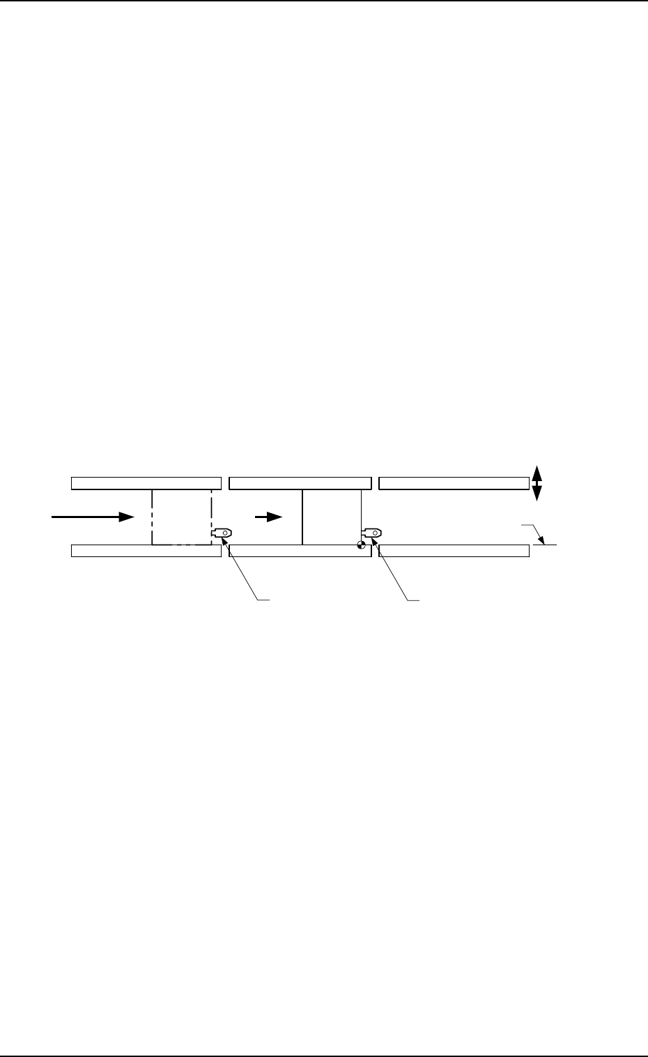
6.3.1 TIM-5100FL
P.C.B. Placement Coordinates Reference: R-FRONT
P.C.B. Transfer Reference: Front Side of Machine
P.C.B. Transfer Direction: L → R
P.C.B. Positioning Reference: R-FRONT
L Conveyor (Input Conveyor)
R Conveyor
(Output Conveyor)
L Conveyor
P.C.B. Stopper
R Conveyor
P.C.B. Stopper
P Conveyor
(P.C.B. Positioning Section)
Movable Side
P.C.B. Transfer Reference
P.C.B.
P.C.B. Flow Direction
A
Fig. 1.21-1
Outline of System Operation
(1) The P.C.B. transferred from the input machine is sent to the P.C.B. stop-
per position of the L conveyor and stops there.
(2) After the P.C.B. at the P.C.B. positioning section has been discharged, the
PCB stopper of the L conveyor descends and the P.C.B. at position A is
sent to the P.C.B. stopper of the R conveyor.
(3) The backup base rises and works to position the P.C.B. vertically and to
align it in the Y direction.
The amount of the backup base rise is numeric-controlled by the
servomotor.
(4) After the P.C.B. positioning has been completed, the machine starts the
P.E.C. recognition operation and the component placement.
(5) After the placement operation has been completed, the positioning is can-
celled, the backup base descends, the P.C.B. stopper of the R conveyor
also descends, and the P.C.B. is transferred onto the R conveyor.
(6) When the backup base lowering has been completed, the P.C.B. discharged
onto the R conveyor is transferred to the output machine, using the R
conveyor.