1OM-1064-002.pdf - 第148页
6. Starting, Emergency Stop, and T emporary Stop (Pause) Operations for Automatic Operation (“PLACE” Mode) (6 ) Open the “AUTO OPN. MODE <PLACEMENT>” display and check the origin marks “ ”. Note: When “ ” marks…

6. Starting, Emergency Stop, and Temporary Stop (Pause) Operations for Automatic Operation (“PLACE” Mode)
6. Starting, Emergency Stop, and Temporary Stop
(Pause) Operations for Automatic Operation
(“PLACE” Mode)
6.1 General Start Procedure
(1) Perform the following operations.
• Preparation of Pattern Program
(Refer to “5.1 Preparation of Pattern Program of Section 2” for details)
• Refer to “5.2 Program Change Operation of Section 2 ” for details.
• Pattern Program Checking for Production Model
(Refer to “5.3 Pattern Program Checking for Production Model of Sec-
tion 2” for details)
“PLACE” must be set in the “PLACEMENT MODE” data box at the
“OPERATION DATA” display in the pattern program.
(The LED of the [PASS/PLACE CHANGE] key at the “AUTO OPN.
SUB-MENU” display illuminates green.)
• Refer to “5.4 Setting of Operation Mode of Section 2” for details.
(2) Confirm that the maintenance covers (maintenance covers, supply
covers, safety bars) are closed.
(3) Set the [OPERATION/SET UP] switch to the “OPERATION” side and
remove the selection key from the machine.
(4) Confirm that the LEDs (-HD09) of the [READY] button on the front and
rear operation panels are “ON”.
Press the [READY] button to turn it on if necessary.
To set the opposite side ready for operation, select the [SIDE A] or the
[SIDE B] key (Only the opposite side can be selected. Press the [READY]
button in the case of the operation panel.) under the label “(FEEDER
CHANGE-OVER PREPARATION COMPLETE)” at the “AUTO OPN
SUB-MENU” display and press the [MOVE] button. (Hierarchical Se-
quence: “AUTO OPN. MODE (PLACEMENT)” Display → “AUTO
OPN. SUB-MENU” Display)
(5) Check the surroundings of the machine and confirm safety before start-
ing the automatic operation.
CAUTION
Check carefully that there is no person around
the moving mechanisms of the machine.
(Especially, the other side of machine opera-
tion)
Make sure that no objects remain within the
moving mechanisms of the machine.
(Tools and Parts)
0004-002 2-49 Tg0246-PM-OP
6. Starting, Emergency Stop, and Temporary Stop (Pause) Operations for Automatic Operation (“PLACE” Mode)
(6) Open the “AUTO OPN. MODE <PLACEMENT>” display and check
the origin marks “”.
Note: When “” marks do not appear before the devices other than
“INPUT MACHINE”, the automatic operation cannot be started.
• When “” marks appear before the devices other than “INPUT MA-
CHINE”, proceed to Step (8).
• When “” marks do not appear before some devices other than “IN-
PUT MACHINE”, proceed to Step (7).
(7) Press the [ZERO] button.
• The “” marks appear before all devices except for “INPUT MA-
CHINE”.
(8) Press the [START] button.
• Work requirement and ready signals are sent to the input machine side.
• When the input machine is set ready for operation, it receives the work
requirement signal from the main machine and right after that, P.C.B.’s
start flowing into the input machine and the automatic operation (place-
ment operation) starts.
When the input machine is not set ready, the machine is set in the
“WAIT” mode.
Reference
z
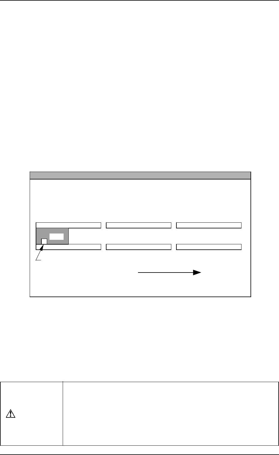
When the machine is operated singly (isolated operation such as an actual component
placement test), a P.C.B. must be put on the input conveyor as shown in the figure
such that the P.C.B. detection sensor is turned ON.
L Conveyer P.C.B. Detection L Sensor (-BPH141)
L Conveyor
(Input Conveyor)
R Conveyor
(Output Conveyor)
P.C.B. Flow Direction
P.C.B.
P Conveyor
(P.C.B. Positioning Section)
The figure shows that a P.C.B. is transferred from left to right when viewed from the
front side of the machine.
• When the automatic operation (component placement operation)
starts, all “” marks (origin marks) disappear and the LED (-HD01)
of the [START] button and the tower light (green) illuminate.
Notes: (a) The machine cannot be started unless the “AUTO OPN.
MODE <PLACEMENT>” display is active.
(b) When a P.C.B. already exists in the P.C.B. positioning sec-
tion, the machine does not place any components on the
P.C.B. and discharges the P.C.B.
CAUTION
To stop the machine immediately in an emergency, press one of the
[EMERGENCY STOP] buttons.
Refer to “6.8.3 Emergency Stop Procedure of Section 2” for details.
Refer to “6.7.2 Reset and Start Procedure from Emergency Stop of
Section 2” for details on how to reset the machine from emergency
stop.
9910-001 2-50 Tg0246-PM-OP

6. Starting, Emergency Stop, and Temporary Stop (Pause) Operations for Automatic Operation (“PLACE” Mode)
6.2 Temporary Stop Procedure
Press the [PAUSE] button.
After the machine runs in its minimum cycle (single operating unit), it stops
running.
Note: “PAUSE” mode does not mean that the machine is completely stopped.
Take ample care when the machine is set in the “PAUSE” mode.
The machine starts running all of a sudden right after it receives a start
signal (a start signal is sent out when the [START] or the [MOVE]
button is pressed).
6.3 Start Procedure from “PAUSE” Mode
Press the [START] or the [MOVE] button while the “AUTO OPN. MODE
<PLACEMENT>” display is active.
• When the [START] button is pressed, the machine starts automatic opera-
tion (“PLACE” Mode) from the step No. which is displayed on the screen.
When the automatic operation (component placement) starts, all origin marks
“” disappear and the LED (-HD01) of the [START] button and the tower
light (green) illuminate.
• When the [MOVE] button is pressed, the machine places the components
related to the step Nos. in the display and is set again in the “PAUSE” mode.
Every time the [MOVE] button is pressed, the machine places components
one by one in the order of step Nos.
While the machine is activated, the LED (-HD02) of the [MOVE] button
illuminates.
9910-001 2-51 Tg0246-PM-OP