1OM-1064-002.pdf - 第217页
Section 4 Manual Mode Menus 9910-001 4-1 Tg0246-PM-OP
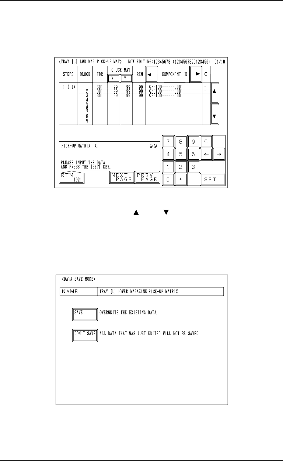
7. Tray Pick-Up Matrix (Option)
• Case: The machine is in the “STOP” or the “PAUSE” mode.
Shown are the matrix positions of the tray components to be picked up sub-
sequently. (Fig. 3.26)
The matrix can be changed while the machine is in the “STOP” or the
“PAUSE” mode.
9910-001 3-46 Tg0246-PM-OP
Fig. 3.26
To change the matrix, press the [ ] or the [ ] key to select the related block.
Select the [X] or the [Y] key, use the ten-key pad to specify the matrix posi-
tion, and press the [SET] key to define the parameters.
After the matrix position is defined, press the [RTN] key.
The “DATA SAVE MODE” display (Fig. 3.27) appears on the screen. To save
the changed matrix position, press the [SAVE] key. Otherwise, press the [DON’T
SAVE] key.
Fig. 3.27

Section 4
Manual Mode Menus
9910-001 4-1 Tg0246-PM-OP
MANUAL AXIS
OPERATION
MANUAL
SUBSYSTEM
OPERATION
ZEROING
OPERATION
PRODUCT
CHANGE
PROGRAM
CHANGE
(3. in Section 4)
(4. in Section 4)
(5. in Section 4)
(6. in Section 4)
(7. in Section 4)
(10. in Section 4)
PCB SUPPORT
PINS SET-UP
MODE
MANUAL
NOZZLE CHANGE
OPERATION
(9. in Section 4)
MANUAL
TRANSFER
OPERATION
(8. in Section 4)
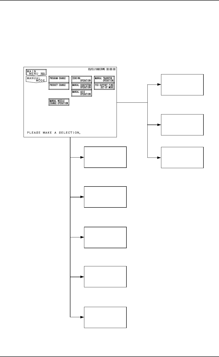
1. Hierarchical Structure of Manual Mode Displays
Manual mode operation is described along with the following hierarchical struc-
ture.
The number in ( ) shows item Nos. to be referred to in the instruction manual.
9910-001 4-2 Tg0246-PM-OP
1. Hierarchical Structure of Manual Mode Displays