1OM-1064-002.pdf - 第138页
5. Preparation and Confirmation before Operation 0103-002 2-40 Tg0246-PM-OP Fig. 2.24-4 Notes: (a) When some components are previously placed on the back of the P .C.B. and P .C.B. support pins are inserted, make sure th…
5. Preparation and Confirmation before Operation
Fig. 2.24-1 Fig. 2.24-2
Fig. 2.24-3
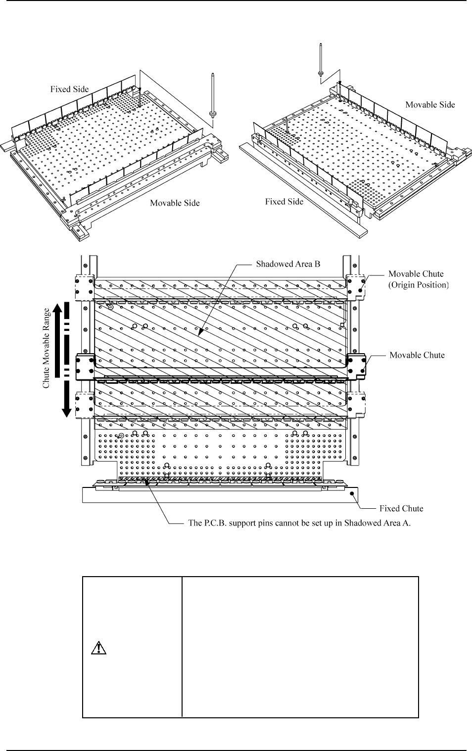
CAUTION
When the automatic set-up operation is imple-
mented with the movable chute (solid line) lo-
cated at the position shown in Fig. 2.24-3, do
not keep the P.C.B. support pins inserted in
Shadowed Area B.
Otherwise, the movable chute may collide with
the P.C.B. support pins because the movable
chute slides out (opening direction) once and
then slides in (closing direction) according to
the program.
9910-001 2-39 Tg0246-PM-OP
Precautions for PCB Support Pin Installation and Removal
5. Preparation and Confirmation before Operation
0103-002 2-40 Tg0246-PM-OP
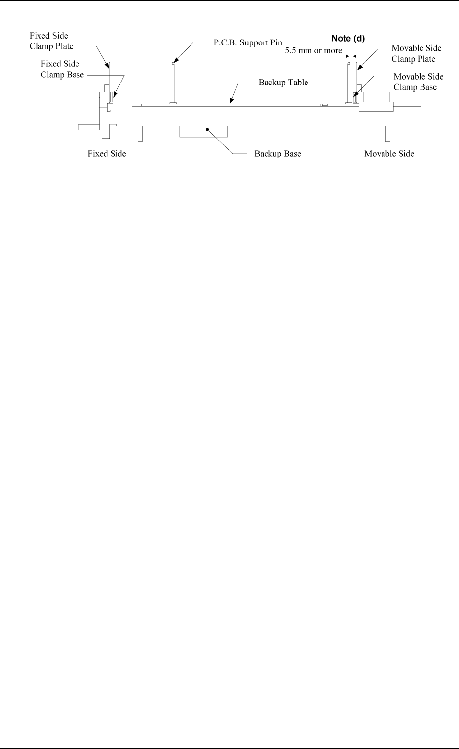
Fig. 2.24-4
Notes: (a) When some components are previously placed on the back of the
P.C.B. and P.C.B. support pins are inserted, make sure that no pin
touches a component.
(b) P.C.B. support pins cannot be inserted into the holes on the backup
table which are located closest to the clamp plate on the fixed
side.
(c) When a component is trapped or dust has accumulated on the
backup table, the height of the P.C.B. support pins cannot be set
correctly. In this case, remove the component or dust with a vacuum
cleaner, etc. (Air Blowing Prohibited)
(d) When the P.C.B. support pins are inserted near the clamp plate on
the movable side, the distance between the center of the holes on
the backup table and the clamp base must be 5.5 mm or more.
5. Preparation and Confirmation before Operation
Beam A Side
Beam B Side
(Front Side of Machine)
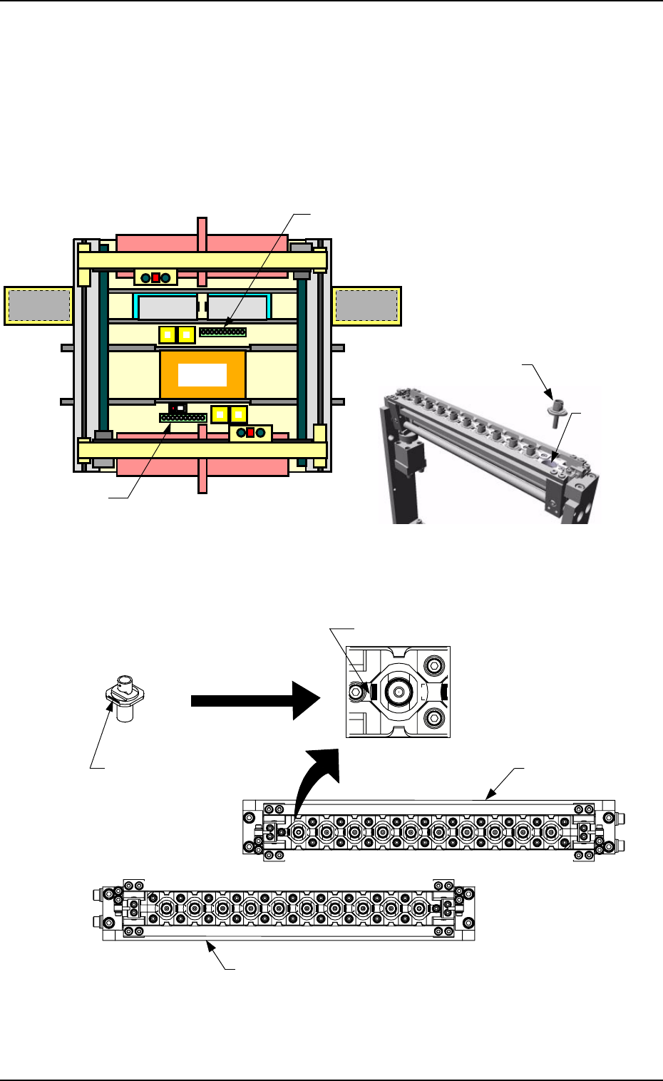
Fig. 2.25-1 Nozzle Stocker Position Fig. 2.25-2 Rough View of Nozzle Stocker
Fig. 2.25-3 Direction of Nozzle Arrangement
Nozzle
Storage Section
Nozzle Stocker B
Nozzle Stocker A
Set the nozzle in the nozzle
stocker, taking care of the
direction of the nozzle.
Imprinted Nozzle ID
Nozzle Stocker A
Nozzle
Imprinted Nozzle ID
Nozzle Stocker
B
Beam B Side
(Front Side of Machine)
5.2.3 Preparation of Nozzle Stocker Section
Set the nozzles (the nozzles to be used in the current program) in the nozzle
storage section of the nozzle stocker.
The nozzles must be set as shown in Fig. 2.25-3.
Direct the imprinted nozzle ID mark as shown in the figure and insert the
nozzle into the groove.
Magnified
View
9910-001 2-41 Tg0246-PM-OP