1OM-1064-002.pdf - 第193页
5. Operation Mode 9910-001 3-24 Tg0246-PM-OP • When “FEEDER” is set in the data box, specify the feeder No. Fig. 3.10-3 • When “HEAD” is set in the data box, specify the head No. “BEAM-A #1”, “BEAM-A #2”, “BEAM-B #1”, or…
5. Operation Mode
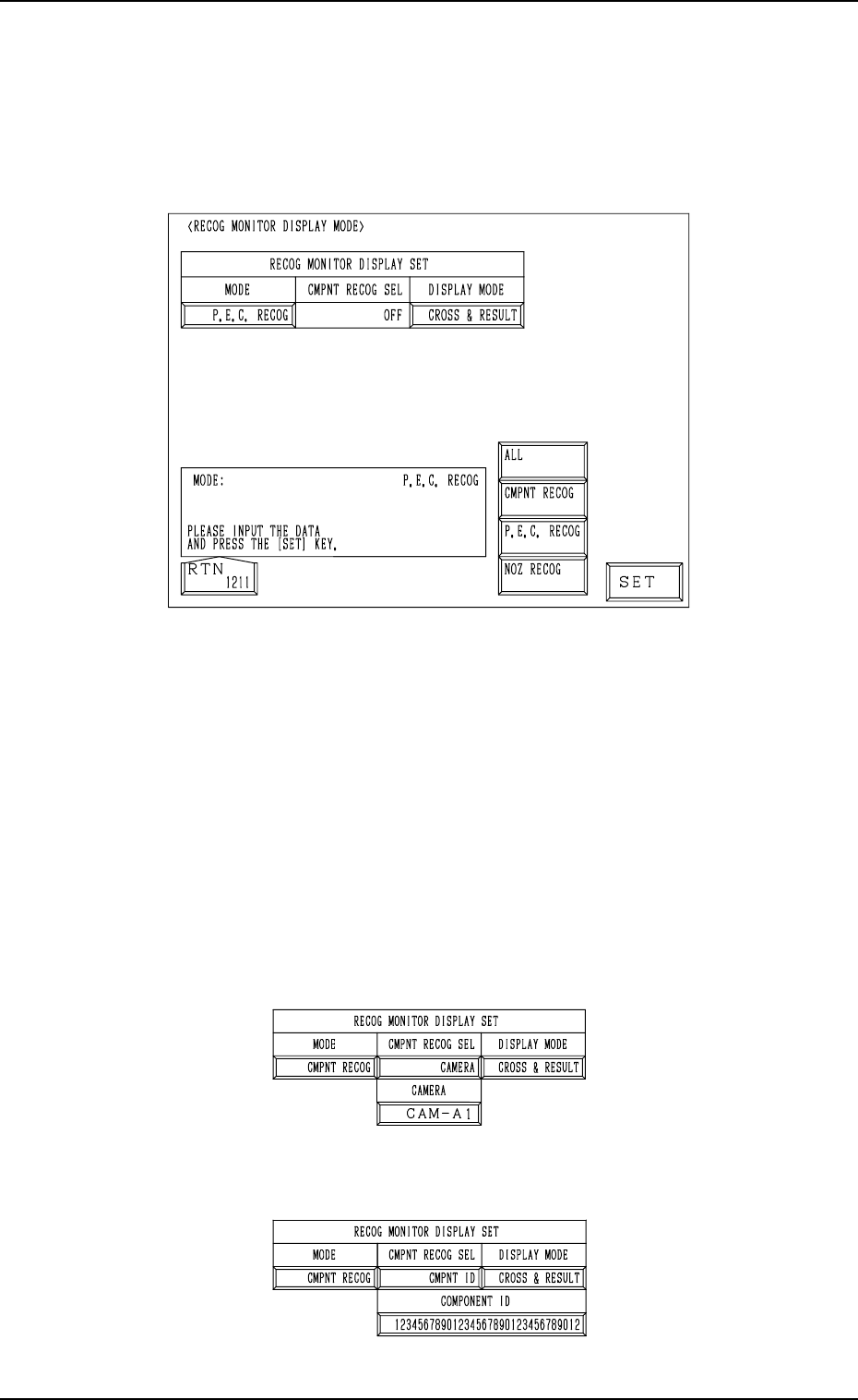
5.3 RECOG MONITOR DISPLAY MODE Display
• It can be specified how to display the results of recognition such as P.E.C.
and component recognition functions on the recognition monitor.
When the [RECOG MONITOR DISPLAY MODE] key is pressed at the “OP-
ERATION MODE” display, the following display appears on the screen.
9910-001 3-23 Tg0246-PM-OP
Fig. 3.9
MODE
Specify the recognition mode which the displayed result should be based
on.
Set “ALL”, “CMPNT RECOG”, “P.E.C. RECOG” or “NOZ RECOG” in
the data box.
CMPNT RECOG SEL
Specify the requirements which the displayed result should be based on
only for the component recognition function.
Set “OFF”, “CAMERA”, “CMPNT ID”, “FEEDER”, “HEAD”, or
“NOZZLE” in the data box.
• When “CAMERA” is set in the data box, specify the camera No.
“CAM-A1”, “CAM-A2”, “CAM-B1”, or “CAM-B2”.
Fig. 3.10-1
• When “CMPNT ID” is set in the data box, specify the component ID.
Fig. 3.10-2
5. Operation Mode
9910-001 3-24 Tg0246-PM-OP
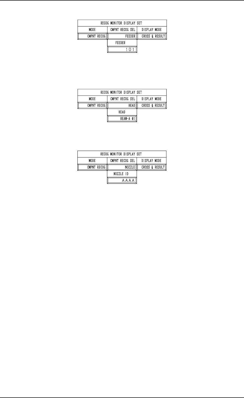
• When “FEEDER” is set in the data box, specify the feeder No.
Fig. 3.10-3
• When “HEAD” is set in the data box, specify the head No. “BEAM-A #1”,
“BEAM-A #2”, “BEAM-B #1”, or “BEAM-B #2”.
Fig. 3.10-4
• When “NOZZLE” is set in the data box, specify the nozzle ID.
Fig. 3.10-5
DISPLAY MODE
Specify the requirements which the displayed result should be based on
only for the component recognition function.
Options: “CROSS”, “CROSS & RESULT”, “OFF”
It is recommended that “CROSS” should be set in the data box.
5. Operation Mode
9910-001 3-25 Tg0246-PM-OP
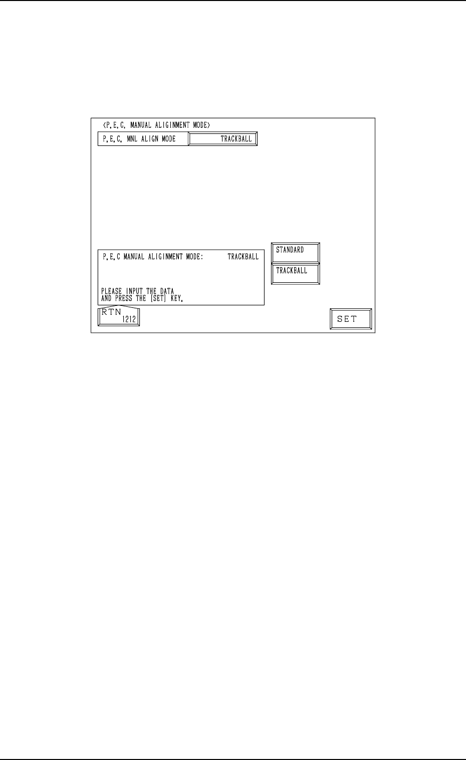
5.4 P.E.C. MANUAL ALIGNMENT MODE Display
• Described below is how to perform the P.E.C. manual alignment operation
after a P.E.C. recognition error has occurred.
When the [P.E.C. MANUAL ALIGNMENT MODE] key is pressed at the
“OPERATION MODE” display, the following display appears on the screen.
Fig. 3.11
When a P.E.C. recognition error has occurred, the fiducial mark position must
be specified through manual alignment operation. “STANDARD” or
“TRACKBALL” can be selected as a manual alignment mode.
STANDARD : When one of the direction keys is selected on the touch screen
(“MANUAL ALIGNMENT” display) and the [MOVE] but-
ton is pressed, the captured image of the component can be
aligned manually.
TRACKBALL : The mark position (a view on the recognition monitor) can
be specified and aligned manually through track ball opera-
tions.