1OM-1064-002.pdf - 第99页
Section 2 Before Automatic Operation 9910-001 2-1 Tg0246-PM-OP
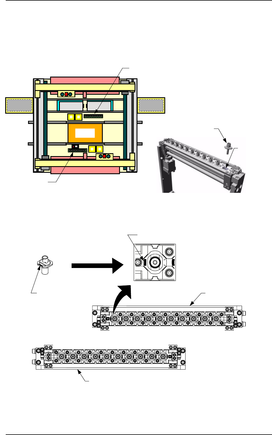
Nozzle Stocker
Set the nozzles in the nozzle storage section of the nozzle stocker.
The nozzles must be set as shown in Fig. 1.32-3.
Direct the imprinted nozzle ID mark as shown in the figure and insert the nozzle
into the groove.
Beam A Side
Beam B Side
Front Side of Machine
Fig. 1.32-1 Nozzle Stocker Position Fig. 1.32-2 Rough View of Nozzle Stocker
Fig. 1.32-3 Direction of Nozzle Arrangement
Nozzle
Storage Section
Nozzle Stocker B
Nozzle Stocker A
Set the nozzle in the nozzle stocker,
taking care of the direction of the
nozzle.
Imprinted Nozzle ID
Nozzle Stocker A
Nozzle
Imprinted Nozzle ID
Nozzle Stocker
B
Beam B Side
Front Side of Machine
8. Vacuum Nozzles
0103-002 1-68 Tg0246-PM-OP
Magnified View

Section 2
Before Automatic Operation
9910-001 2-1 Tg0246-PM-OP

1. Notes
1. Notes
1.1 [PNL CHANGE] Buttons
• The front and rear operation panels are provided with a [PNL CHANGE]
button.
• Operations are performed with the keys on the touch screen and the buttons
and switches on the operation panels. To avoid any danger, either one of the
front and rear operation panels including the touch screens can be set avail-
able in operation.
• It is impossible to activate both operation panels, including the touch screen
at the same time.
• When one of the operation panels is active (set available in operation), the
LED (-HD05) of the [PNL CHANGE] button illuminates. (Operation Pos-
sible)
• When one of the operation panels is not active, the LED (-HD05) of the
[PNL CHANGE] button extinguishes. (Operation Impossible)
• Listed below are valid buttons when the [PNL CHANGE] button is pressed.
Touch Screen Switch
[START] Button
[RESET] Button
[ZERO] Button
[MOVE] Button
[SYS CLR] Button
• The following buttons can be activated anytime regardless of the [PNL
CHANGE] buttons.
[STOP] Button
[PAUSE] Button
• When the [PNL CHANGE] button on the available operation panel is pressed,
the LED (-HD05) of the button goes on and the LED (-HD06) illuminates,
indicating that the operation is locked.
• When the LED (-HD06) on the front panel illuminates, the LED (-HD06) on
the rear panel also goes on.
• When the operation is locked, the [PNL CHANGE] buttons become un-
available.
• To cancel “LOCK” mode, press the [PNL CHANGE] button on the avail-
able side again.
“LOCK” mode is canceled and the LED (-HD06) extinguishes.
• When the [SYS CLR] button on the operation panel in “LOCK” mode is
pressed, the “LOCK” mode is canceled.
9910-001 2-2 Tg0246-PM-OP