1OM-1064-002.pdf - 第185页
4. SEMI-AUTOMA TIC OPERA TION 9910-001 3-16 Tg0246-PM-OP 4.2 Selection of W ARM or COLD Start Operation When steps for which components are not placed exist (placement steps for the warm start function exist) and the [SE…

4. SEMI-AUTOMATIC OPERATION
*10 [FULL AUTO CONT [START]] Key
This key is used to specify the continuous operation from the operation
start step No.
When the [START] button is pressed after this key is selected, the “AUTO
OPN MODE (PLACEMENT)” display appears on the screen and auto-
matic operation starts.
Note: FULL AUTO CONT: Normal automatic operation is performed
continuously from the steps specified in the “U-NO”, “P-NO” and
“O-NO” data boxes.
*11 [FULL AUTO STEP [MOVE]] Key
This key is used to specify step operation from the operation start No.
When the key is selected and the [MOVE] button is pressed, the “AUTO
OPN MODE (PLACEMENT)” display appears on the screen and auto-
matic operation starts.
When the machine is set in the “PAUSE” mode, the automatic operation
stops once because this is a step operation.
Note: FULL AUTO STEP: Every time the [MOVE] button is pressed,
step operation is performed from the steps specified in the “U-
NO”, “P-NO”, and “O-NO” data boxes.
*12 [1 CMPNT PLACE [MOVE]] Key
This key is used to specify placement of one component in the operation
start step No.
When this key is selected and the [MOVE] button is pressed, the machine
places only one component in the operation start step No. After that, all
devices return to their origins and stop.
Note: 1 CMPNT PLACE: The machine places only one component in
the steps specified in the “U-NO”, “P-NO”, and “O-NO” data
boxes.
9910-001 3-15 Tg0246-PM-OP
4. SEMI-AUTOMATIC OPERATION
9910-001 3-16 Tg0246-PM-OP
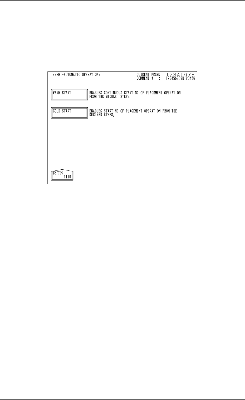
4.2 Selection of WARM or COLD Start Operation
When steps for which components are not placed exist (placement steps for
the warm start function exist) and the [SEMI-AUTOMATIC OPERATION]
key is selected at the “AUTO OPN SUB-MENU” display, the “SEMI-AUTO-
MATIC OPERATION” display (Fig. 3.4) appears on the screen, enabling the
selection of the [WARM START] or the [COLD START] key.
Fig. 3.4
[WARM START] Key
When this key is selected, the “WARM START” display appears on the
screen, enabling the continuous starting of the placement operation from
the middle steps (from the steps for the interrupted P.C.B.).
[COLD START] Key
When this key is selected, the “SEMI-AUTOMATIC OPERATION” dis-
play (Fig. 3.3) appears on the screen, enabling the starting of the placement
operation from the desired steps.
4. SEMI-AUTOMATIC OPERATION
*1
*8
*2
*5
*6
*3
*4
*7
*10
*9
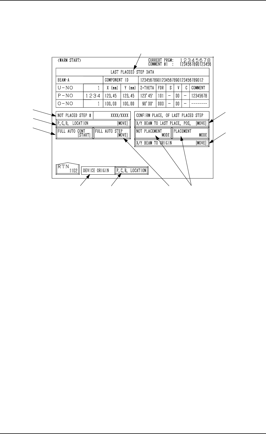
4.3 Warm Start
When the [WARM START] key is pressed at the “SEMI-AUTOMATIC OP-
ERATION” display, the following display appears on the screen.
9910-001 3-17 Tg0246-PM-OP
Fig. 3.5
*1 LAST PLACED STEP DATA
Shown under this label is the step data related to the component which
was placed last on the P.C.B.
*2 NOT PLACED STEP #
Shown in the text box is the number of steps for which components are
not placed. ({{/XX)
{{ : Number of steps for which components are not placed (the num-
ber of steps for which components are to be placed after the warm
start operation)
XX : Total Number of Pattern Program Steps
*3 DEVICE ORIGIN
This indicates whether or not the devices are zeroed.
• Label Color Coding
Devices at Origins: Green
Devices Not at Origins: Light Red
*4 [P.C.B. LOCATION] Key
This display section indicates how the P.C.B. is positioned.
When a P.C.B. is correctly positioned, this key turns green.
When there is no P.C.B. or a P.C.B. is not positioned correctly, this key
turns light red.
When the [P.C.B. LOCATION] key is pressed, the “MANUAL TRANS-
FER OPERATION” display appears on the screen.
Refer to “8. Manual Transfer Operation of Section 4” for details.
When *3 and *4 are green, it indicates that the P.C.B. positioning opera-
tion is set ready.