1OM-1064-002.pdf - 第89页
7. Construction of Feeder Carriages Number of Installable Feeders (1) T ape Feeders Max. 76 feeders (when only 8 mm tape feeders are used) (Max. 38 feeders when only 12 mm tape feeders are used) (Max. 36 feeders when onl…
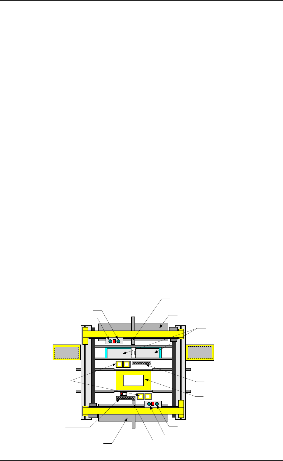
6.4 Placement Heads
Basically, the cycle *1 through *6 is repeated alternately on both Beams A and
B (placement heads).
The placement heads work according to the condition specified in the pattern
program, etc.
*1 P.C.B. Recognition (Placement Position)
Individual components on the P.C.B. are recognized to detect the positional
deviations (deviations of component placement positions).
(This recognition is performed only when the function is enabled in the
pattern program.)
*2 Nozzle Change Operation
A proper vacuum nozzle is selected for components and the attached nozzle
is replaced with the proper one.
The vacuum nozzle on the placement head is stored in the nozzle stocker
and the required vacuum nozzle is taken out of the stocker.
*3 Component Pick-Up (Tape Feeder, Vibratory Stick Feeder,
Multi-Layer Tray Feeder)
Components are supplied from the feeder which corresponds to the pattern
program and the vacuum nozzle picks them up.
In normal cases, one beam is used to pick up two pieces of components of
Heads #1 and #2.
Tape feeders, vibratory stick feeders, and multi-layer tray feeders are pre-
pared. (Each feeder is optional.)
*4 Component Recognition
The image of the picked component is captured by the component recogni-
tion camera and recognized by the recognition unit to detect the deviation
in the pick-up position.
*5 Component Placement
Components are placed.
The machine corrects the deviations of the P.C.B. and the components de-
termined through P.E.C. and component recognition and places the compo-
nents accurately on the specified positions.
In normal cases, one beam is used to place two pieces of components of
Heads #1 and #2.
*6 Rejected Component Discharge Operation
The components rejected as a recognition error are discharged.
6. Outline of System Operation
9910-001 1-58 Tg0246-PM-OP
*6
Rejected Component Discharge
(Component Storage Box)
*3
Component Pick-Up
(Tray)
*2
Nozzle Change Operation
(Nozzle Stocker)
*1
P.C.B. Recognition
(P.E.C. Camera)
*5
Component Placement
*4
Component Recognition
(Component Recog-
nition Camera)
Head #2
Beam A Side
*3
Component Pick-Up
(Tape and Vibratory Stick Feeders)
Beam B Side
Head #1
*2
Nozzle Change Operation
(Nozzle Stocker)
*6
Rejected Component Discharge
(Component Storage Box)
Head #2
Head #1
*3
Component Pick-Up
(Tape and Vibratory Stick Feeders)
Fig. 1.25
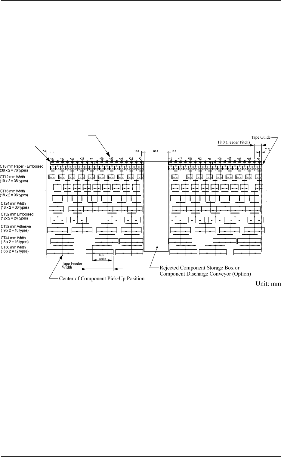
7. Construction of Feeder Carriages
Number of Installable Feeders
(1) Tape Feeders
Max. 76 feeders (when only 8 mm tape feeders are used)
(Max. 38 feeders when only 12 mm tape feeders are used)
(Max. 36 feeders when only 16 mm tape feeders are used)
(Max. 36 feeders when only 24 mm tape feeders are used)
(Max. 24 feeders when only 32 mm tape feeders are used)
(Max. 18 feeders when only 32 mm adhesive tape feeders are used)
(Max. 16 feeders when only 44 mm tape feeders are used)
(Max. 12 feeders when only 56 mm tape feeders are used)
(Max. 12 feeders when only 72 mm tape feeders are used)
Tape Guide
FDR No. (Feeder Slot No.)
Fig. 1.26
Note: Fig. 1.26 shows the maximum number of installable feeders, assuming
that the same type of feeders are installed. The location of tape feeders
is just one example.
Maximum Number of Installable Feeders = Number of Installable Feed-
ers on Beam A or B × 2
7. Construction of Feeder Carriages
0103-003 1-59 Tg0246-PM-OP
7. Construction of Feeder Carriages
9910-001 1-60 Tg0246-PM-OP
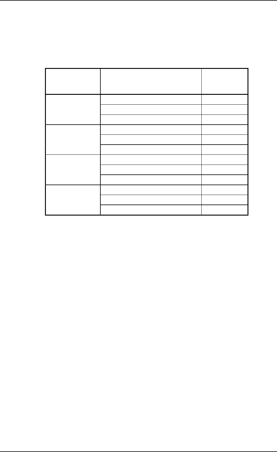
(2) Stick Feeder (Vibratory)
Max. 12 feeders (when only vibratory stick feeders are installed)
One vibratory stick feeder occupies six feeder slot Nos. (lanes).
The following shows the feeder slot Nos. (lanes) for which vibratory stick
feeder units can be registered.
Table 1.8
(3) Tray Feeders
Max. 2 Feeders (Up to 360 types can be used)
Ref.: Tray feeders do not give any effect to the number of installable
tape and stick feeders.
Note: The number of installable feeders varies according to the combination
of tape and stick feeders. Consult our sales personnel for details.
Feeder Base
Nos.
Unit Nos.
Occupied
Lanes
(FDR NO)
Vibratory Stick Feeder Unit #1 101 to 106
Feeder Base #1 Vibratory Stick Feeder Unit #2 107 to 112
Vibratory Stick Feeder Unit #3 113 to 118
Vibratory Stick Feeder Unit #4 121 to 126
Feeder Base #2 Vibratory Stick Feeder Unit #5 127 to 132
Vibratory Stick Feeder Unit #6 133 to 138
Vibratory Stick Feeder Unit #7 201 to 206
Feeder Base #3 Vibratory Stick Feeder Unit #8 207 to 212
Vibratory Stick Feeder Unit #9 213 to 218
Vibratory Stick Feeder Unit #10 221 to 226
Feeder Base #4 Vibratory Stick Feeder Unit #11 227 to 232
Vibratory Stick Feeder Unit #12 233 to 238