1OM-1064-002.pdf - 第241页
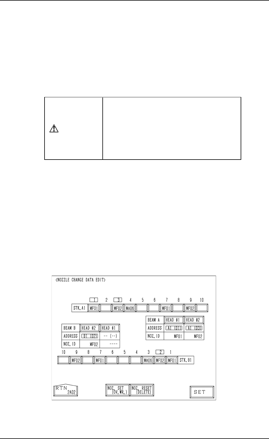
(3) Select the key in the head section for the backup memory condition to be corrected. Then, choose the [NOZ. SET (OV . WR.)] or the [NOZ. RE- SET (DELETE)] key and press the [SET] key . (4) After all head condition is …
9. Manual Nozzle Change Operation
Rewriting Operation of Backup Memory
• The backup memory is used to manage which nozzles are attached to which
heads.
• The actual condition of the nozzle attachment may not match the condition
(information) stored in the backup memory in the handling, etc., after an
error has occurred in nozzle attachment or storage operation. When the ma-
chine is operated under such condition, trouble (collision, wrong placement,
etc.) will result. Therefore, it is required to rewrite the data stored in the
backup memory.
CAUTION
When the backup memory is rewritten by mis-
take, a possible source of trouble will be cre-
ated.
Special care and verification are required while
the data is being rewritten.
Only the person in charge of rewriting should
perform the rewriting operation.
Procedure for Rewriting Operation
(1) Open the “MANUAL NOZZLE CHANGE OPERATION” display (Fig.
4.12) to check how the nozzles are attached and how the data is stored in
the backup memory.
• When the actual condition of the nozzle attachment matches the condi-
tion (data) stored in the backup memory, it is not necessary to rewrite
the data.
• When the actual condition does not match the data stored in the backup
memory, proceed to Step (2).
(2) When the “MANUAL NOZZLE CHANGE OPERATION” display (Fig.
4.12) is active and the [RESET] and [STOP] buttons are pressed at the
same time, the following display (hidden one) appears on the screen.
Fig. 4.13
9910-001 4-24 Tg0246-PM-OP

(3) Select the key in the head section for the backup memory condition to be
corrected. Then, choose the [NOZ. SET (OV. WR.)] or the [NOZ. RE-
SET (DELETE)] key and press the [SET] key.
(4) After all head condition is rewritten completely, press the [RTN] key.
The “DATA SAVE MODE” display appears on the screen, asking whether
or not the corrected data should be saved.
(5) Verify the rewritten contents and compare them with the actual condi-
tion.
(6) Select the [SAVE] or the [DON'T SAVE] key.
When either one of the keys is selected, the “MANUAL NOZZLE
CHANGE OPERATION” display resumes with the information in the
backup memory being updated.
9. Manual Nozzle Change Operation
9910-001 4-25 Tg0246-PM-OP
*8
*9
*7
*1
*2
*3
*4
*5
*6
10. P.C.B. Support Pins Set-Up Mode
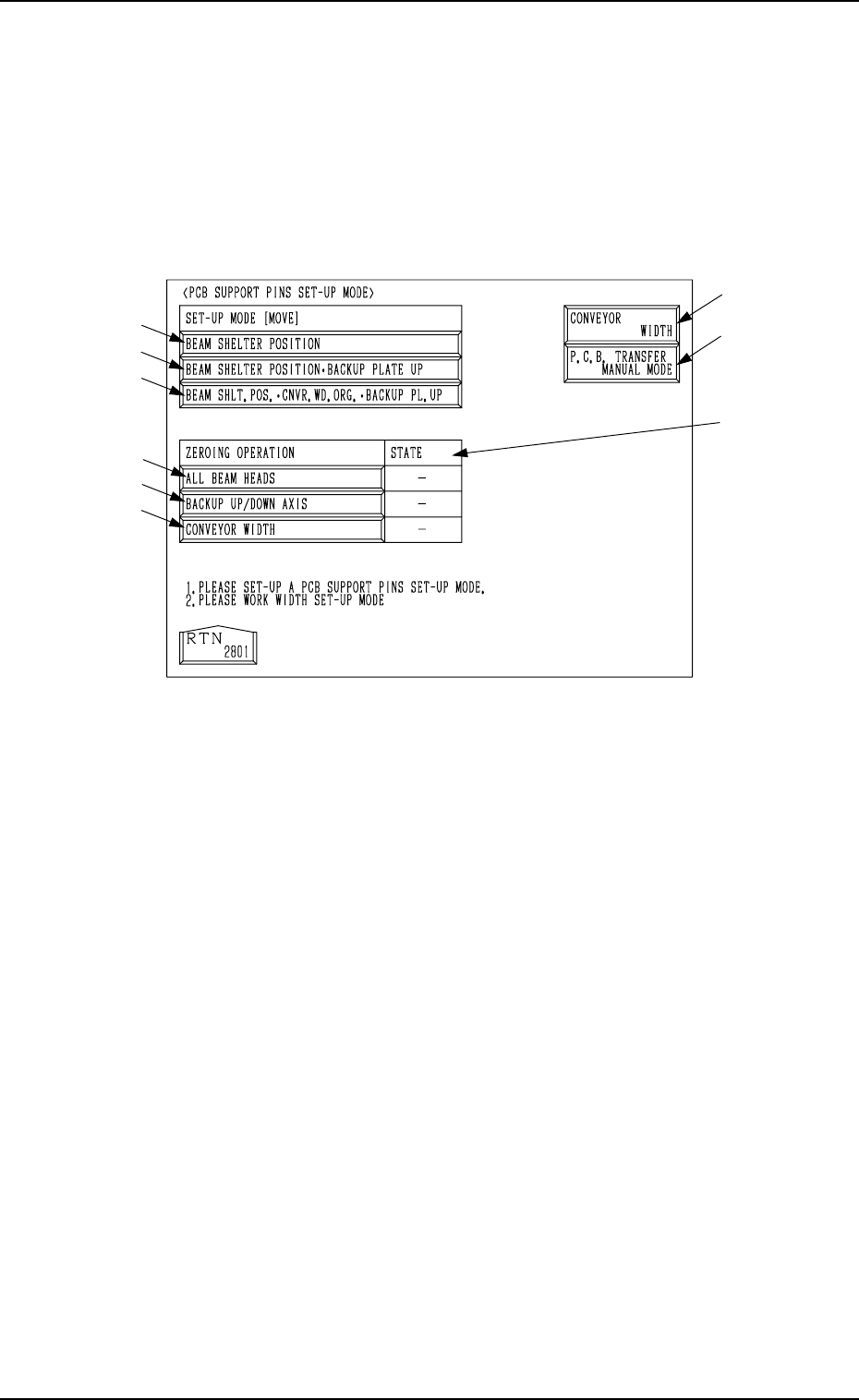
When the [PCB SUPPORT PINS SET-UP MODE] key is pressed at the
“MANUAL MODE” display, the following display appears on the screen.
This display enables the setting of the environmental condition required to
specify the position of the P.C.B. support pins.
Refer to “5.2.2 Adjustment of P.C.B. Positioning Section of Section 2” for the
procedure to specify the position of the P.C.B. support pins.
0004-002 4-26 Tg0246-PM-OP
10. P.C.B. Support Pins Set-Up Mode
Fig. 4.14
*1 [BEAM SHELTER POSITION] Key
When this key is selected and the [MOVE] button is pressed, both beams A
and B retreat to the rear side (Side A).
*2 [BEAM SHELTER POSITION
•
BACKUP PLATE UP] Key
When this key is selected and the [MOVE] button is pressed, both beams A
and B retreat to the rear side (Side A) and the backup plate (base) moves
up.
*3 [BEAM SHLT. POS. CNVR. WD. ORG.
•
BACKUP PL. UP] Key
When this key is selected and the [MOVE] button is pressed, both beams A
and B retreat to the rear side (Side A), the conveyor widens (opens) to the
origin position, and the backup plate moves up.
Ref.: Before the conveyor width set-up operation is initiated, each con-
veyor is automatically activated to check that no P.C.B. is located at
any irregular position.
*4 [ALL BEAM HEADS] Key
When this key is selected and the [MOVE] button is pressed, both beams A
and B are zeroed.
*5 [BACKUP UP/DOWN AXIS] Key
When this key is selected and the [MOVE] button is pressed, the backup
plate is zeroed.