1OM-1064-002.pdf - 第52页
3. Functions 9910-001 1-22 Tg0246-PM-OP 3.3 Equivalent Repetitive Pattern Function Pattern program data for unit P .C.B.’ s (same repetitive patterns) can easily be created through a combination of coordinate data of rep…
3. Functions
9910-001 1-21 Tg0246-PM-OP
3. Functions
3.1 Component Recognition Function
In the component recognition system, an image of the picked component is cap-
tured by the component recognition camera, image-processed, and recognized
by the recognition device. The deviation from the specified pick-up position is
corrected based on the results of the recognition for accurate component place-
ment.
The machine is basically designed to recognize all components and correct the
positional deviations for accurate component placement.
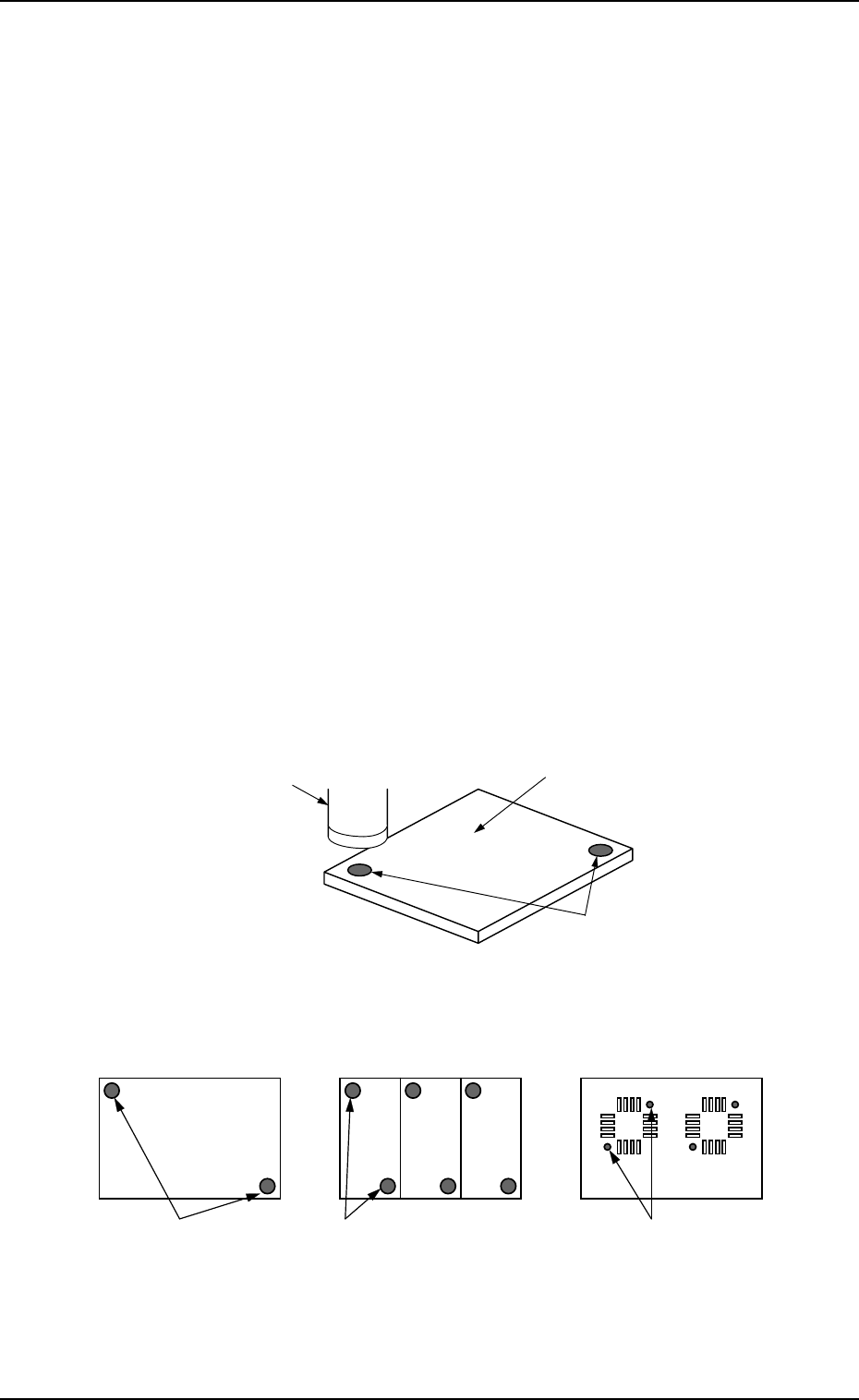
3.2 P.E.C. Recognition Function
An image of the fiducial mark on the P.C.B. is captured by the P.E.C. camera,
image-processed, and recognized by the recognition device. The positional de-
viation of the positioned P.C.B. is corrected based on the results of the recogni-
tion.
• Global P.E.C. Recognition: The whole area of a P.C.B. is recognized to glo-
bally correct the positional deviations.
• Image P.E.C. Recognition: Fiducial marks are put on each unit P.C.B. of a
multi-unit P.C.B. and recognized to correct the positional deviation of each
unit P.C.B.
• Local P.E.C. Recognition: Fiducial marks are put for each individual compo-
nent placement points and recognized to correct the positional deviation of
each point on the P.C.B.
Fig. 1.1
Fig. 1.2
P.C.B.
Recognition Camera
Fiducial Marks
Local P.E.C. Recognition
Image P.E.C. Recognition
(Multi-Unit P.C.B.)
Global P.E.C. Recognition
Fiducial Marks
Fiducial MarksFiducial Marks
Refer to “2.3.2 Operation Data (P.E.C. Recognition) of Section 2 in Volume 2”
for details.
3. Functions
9910-001 1-22 Tg0246-PM-OP
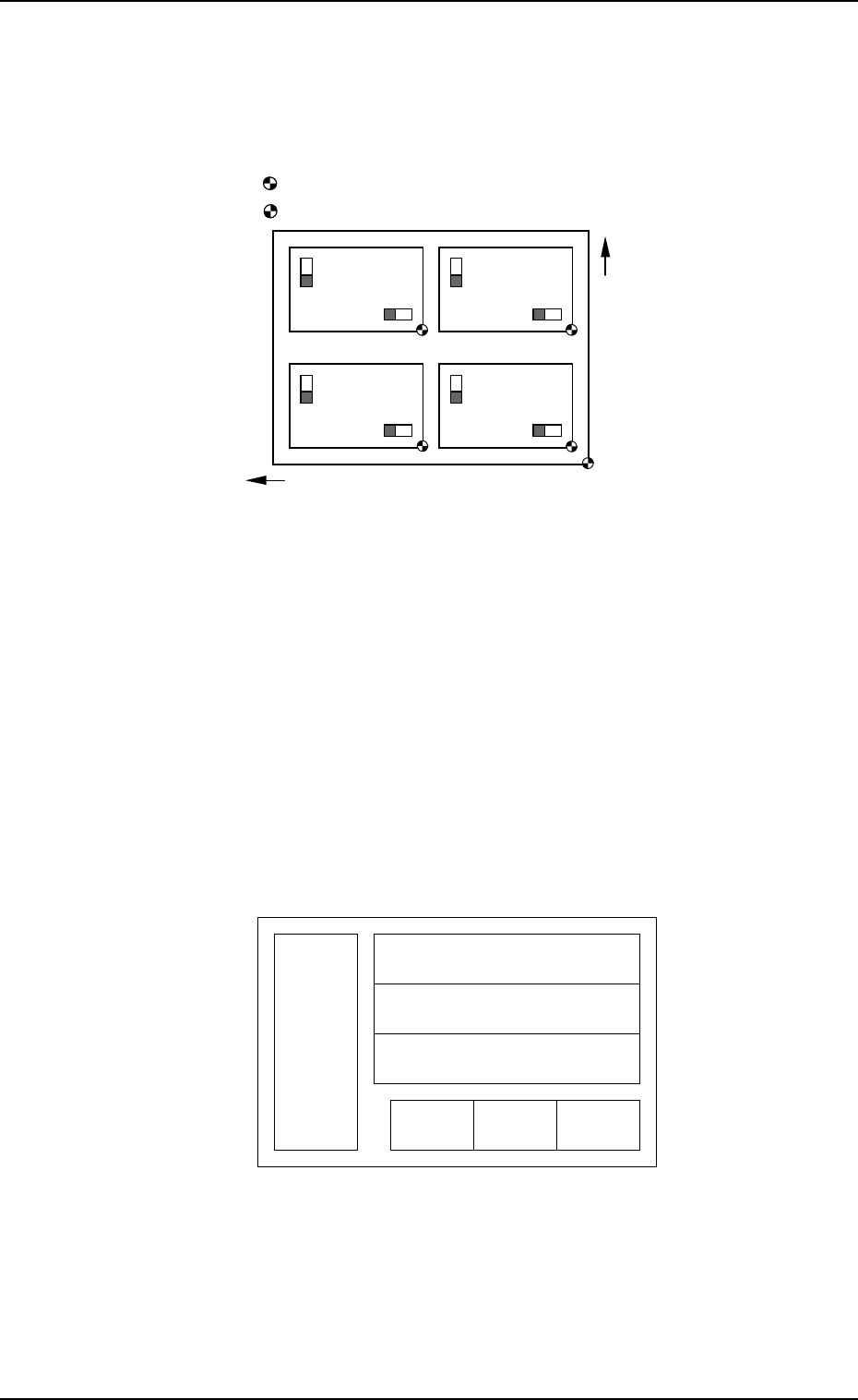
3.3 Equivalent Repetitive Pattern Function
Pattern program data for unit P.C.B.’s (same repetitive patterns) can easily be
created through a combination of coordinate data of repetitive placement pat-
terns and each placement pattern origin.
The center of mark is P.C.B. positioning reference.
The center of mark is Pattern Origin.
Fig. 1.3
Refer to “2.6.3 PLACEMENT DATA (O) Display [Repetitive Placement
Data] of Section 2 in Volume 2” for details.
3.4 Function for Multi-Model Repetitive Patterns
(Application for Un)
By preparing several placement data in one pattern program, it becomes
possible to easily create a pattern program which covers the mixed patterns
for different models in equivalent P.C.B.’s.
A repetitive pattern can be set independently in each placement data.
Example: This function is used for such a P.C.B. as shown below.
Pattern A (3) Pattern A (1)Pattern A (2)
Pattern B (1)
Pattern B (2)
Pattern B (3)
Pattern C
Fig. 1.4
Refer to “3.2.5 Placement Data for Multi-Model Repetitive Patterns (Applica-
tion for Un) of Section 2 in Volume 2” for details.
Y Direction
X Direction

3.5 Priority Sorting Function
By entering a numeral code “0 to 9” in the “C” data field in the placement (P)
data, the component placement sequence is changed and number of nozzle change
times is reduced to avoid deterioration of productivity.
Refer to “3.2.6 Placement Data for Priority Sorting Function of Section 2 in
Volume 2” and “3.2.7 Priority Sorting Application for Multi-Model Repetitive
Patterns of Section 2 in Volume 2” for details.
3.6 Component Library
A set of data related to component placement is organized as a group of specific
component data (information) and managed as a data base in the form of a
component library.
As each component data is created and managed as a component library, it is
not necessary to create component data for each individual pattern programs,
greatly shortening the time for pattern program data creation and editing.
Refer to “COMPONENT LIBRARY” for details.
3.7 Automatic Feeder Axis Adjustment Function
The machine is provided with the recognition function which corrects the posi-
tional deviation of the picked component for accurate component placement.
By feeding the recognized amount of correction back to the pick-up position, the
pick-up position can be brought close to the specified one, realizing the stable
component picks.
Refer to “5.1 AUTOMATIC FEEDER AXIS ADJUSTMENT MODE Dis-
play of Section 3 ” for details.
3.8 Automatic Recovery Function (Reserved Data)
Compared with the normal operation mode in which the machine immediately
stops for component replenishment (priority) after a component shortage or
processing error is detected, this function makes the machine continue to
pick up components from another feeder without picking up components from
the feeder where the component shortage error has occurred. When all unit
PCBs are finished with some components missing, the machine stops in a
state which allows component supply. When pick-up operation is re-started
after the empty feeder is replaced with a full feeder, components are
placed on the component-missing areas on the processed PCBs. When a
component shortage error occurs in the automatic recovery mode, an error
message will prompt the operator to supply the components; but the machine
continues to pick up components from the other feeders and place them on
PCBs. When component shortage errors occur in a different feeder over a
short interval, the feeders can all be replenished collectively with
components to reduce loss time.
3. Functions
9910-001 1-23 Tg0246-PM-OP