1OM-1064-002.pdf - 第171页
2. AUTO OPN MODE (PLACEMENT) Display 2 . AUT O OPN MODE (PLACEMENT) Display When the [AUTO OPN MODE] key is pressed at the “MAIN MENU” display , the following display appears on the screen. Automatic operation of the mac…
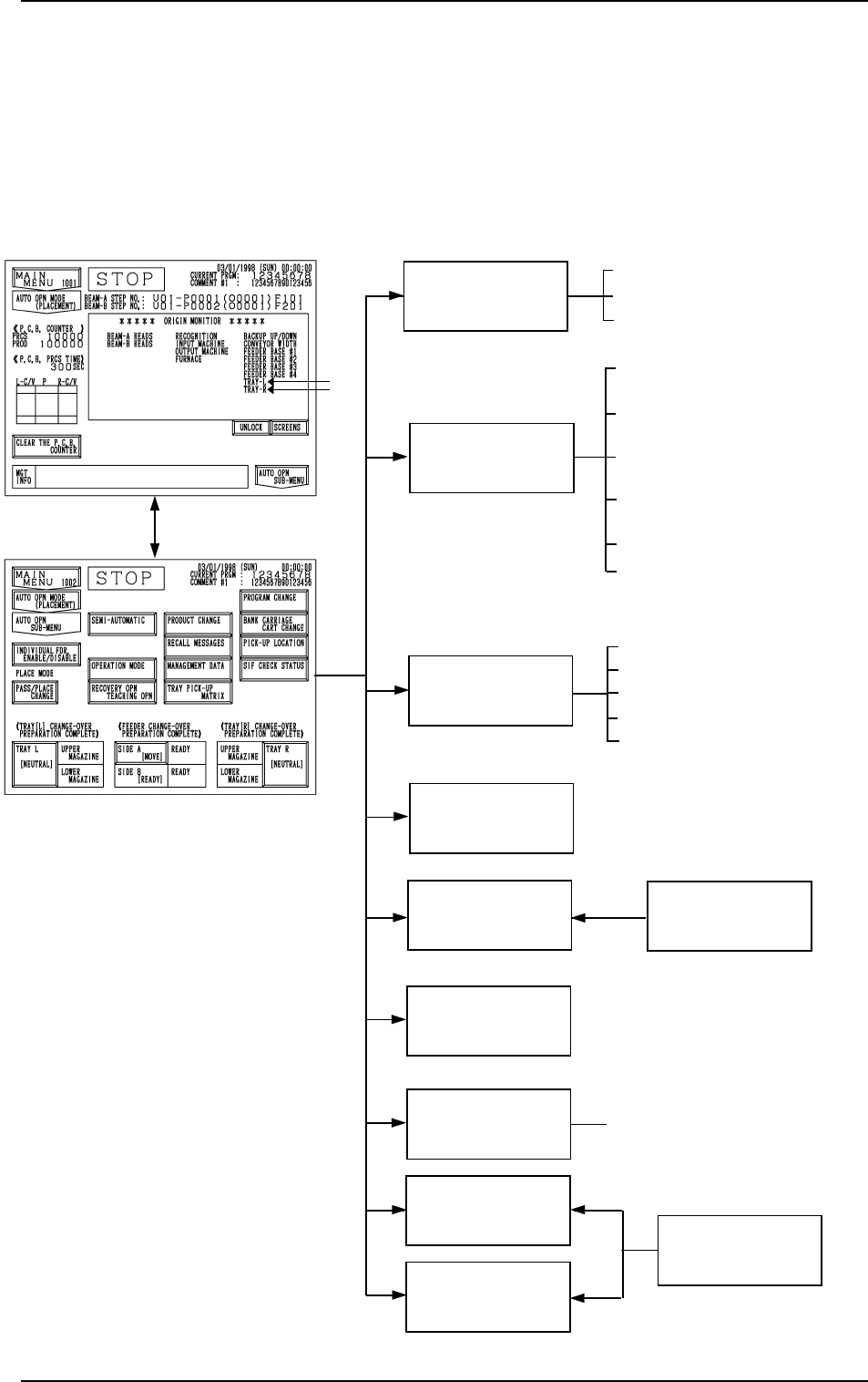
1. Hierarchical Structure of Automatic Operation Dis-
plays
Automatic operation menus are described in the following hierarchical struc-
ture.
The number in ( ) shows item Nos. to be referred to in the instruction manual.
RECALL
MESSAGES
MANAGEMENT
DATA
PRODUCT
CHANGE
TEACH OFFSET
RECOVERY OPN.
TEACHING OPN.
OPERATION MODE
SEMI-AUTOMATIC
OPERATION
(4. in Section 3)
(5. in Section 3)
(6. in Section 3)
(4. in Section 4)
[AUTO OPN. SUB-MENU]
Key
SPECIAL SEL.
(Section 3 in Volume 4)
• FULL AUTO CONT [STRAT]
• FULL AUTO STEP [MOVE]
• 1 CMPNT PLACE [MOVE]
• ALTERNATE MODE
• CONVEYOR WIDTH
: Options
TRAY PICK-UP
MATRIX (Option)
(7. in Section 3)
PICK-UP
LOCATION
• CURRENT PROGRAM
• COMPONENT LIBRARY EDIT
• COMP. CARRIAGE DATA EDIT
• FEEDER (B) OFFSET
• CURRENT PROGRAM PLACE-
MENT DATA SORTING
(Item 6. of Section 3 in Volume 4)
PROGRAM
CHANGE
(3. in Section 4)
• COMPONENT MISSING CHECK
MODE
• AUTOMATIC FEEDER AXIS
ADJ. MODE
• OVERALL TACT TIME REDUC
TION
• RECOG MONITOR DISPLAY
MODE
• P.E.C. MANUAL ALIGNMENT
MODE
1. Hierarchical Structure of Automatic Operation Displays
0103-003 3-2 Tg0246-PM-OP
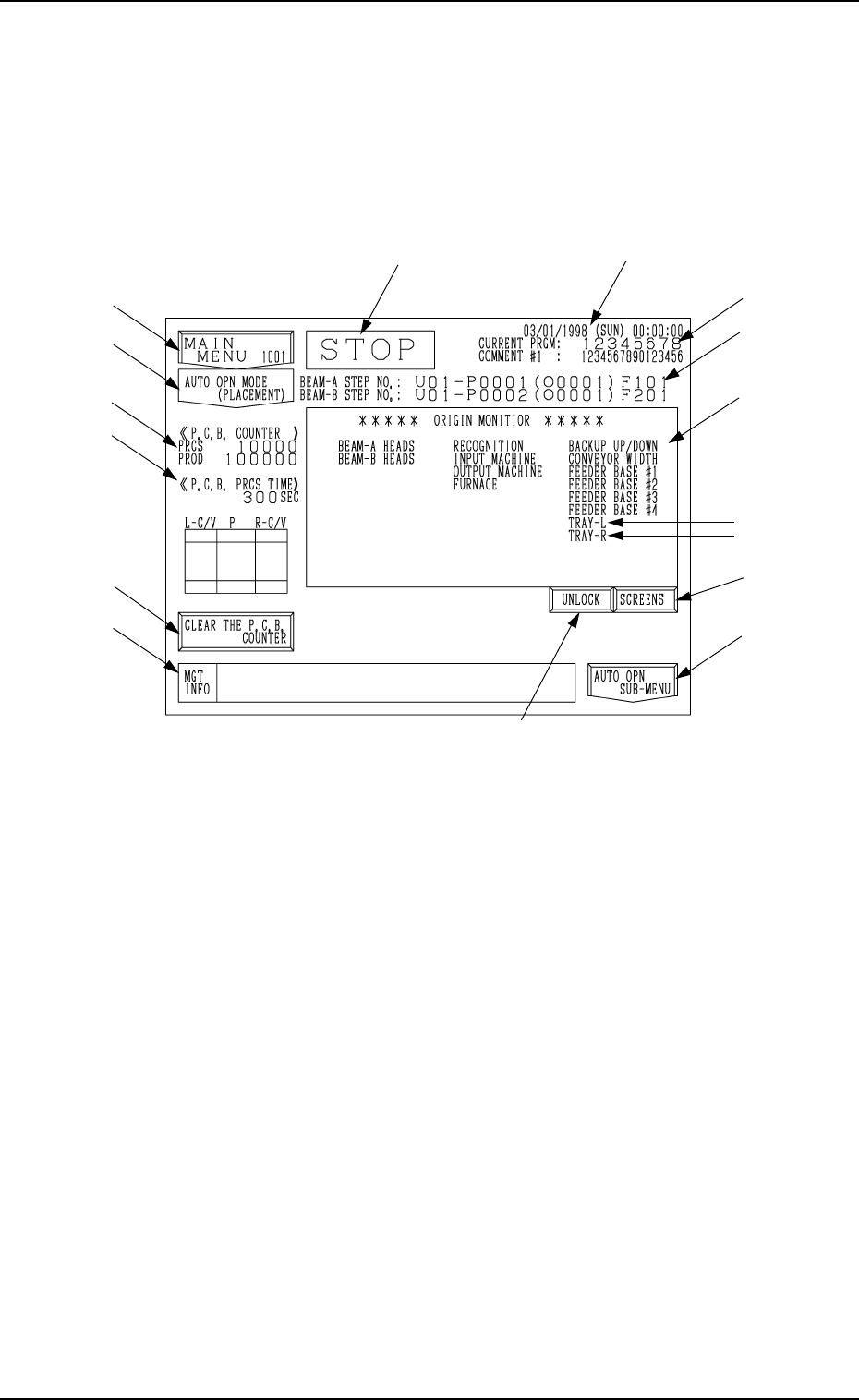
2. AUTO OPN MODE (PLACEMENT) Display
2. AUTO OPN MODE (PLACEMENT) Display
When the [AUTO OPN MODE] key is pressed at the “MAIN MENU” display,
the following display appears on the screen.
Automatic operation of the machine can only be started while this dis-
play is active.
Note: The -marked items are optional.
Fig. 3.1
*1 Current Date and Time
*2 Current Program Name and Comment #1
*3 Step and Feeder Nos. of Placed Component
Indicated are the placement step Nos. for the heads on Beams A and B.
“U01” represents the U-No. (block No.) of the current pattern program
(program being executed).
“O0001” is a repetitive pattern No. and appears only when repetitive pat-
terns are set.
*4 Current Operation Mode
(RUN, PAUSE, STOP, or WAIT)
*5 [MAIN MENU] Key
When this key is pressed, the “MAIN MENU” display appears on the
screen.
0103-003 3-3 Tg0246-PM-OP
*1
*4
*14
*3
*11
*9
*10
*8
*7
*6
*5
*2
*12
*13
2. AUTO OPN MODE (PLACEMENT) Display
DEVICE TESTDEVICE TEST
(PLACEMENT)
(
PASSAGE
)
9910-001 3-4 Tg0246-PM-OP
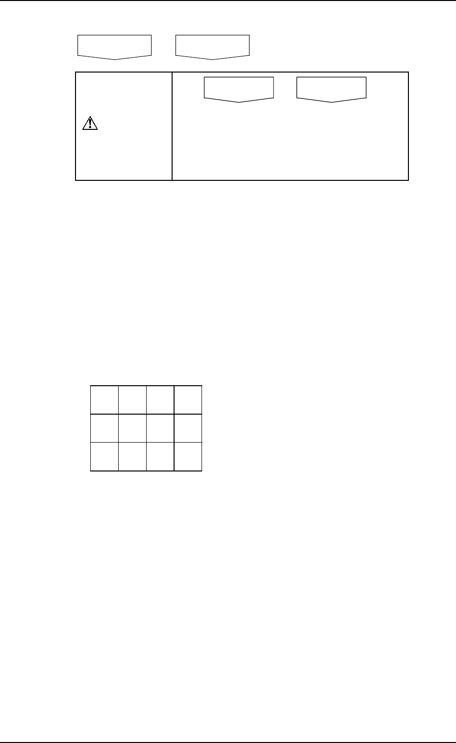
*6 Normally the key is labeled as follows.
CAUTION
Do not perform automatic operation when the
key is labeled as “DEVICE TEST (PLACE-
MENT)” or “DEVICE TEST (PASSAGE)”.
Normal automatic operation cannot be per-
formed because test mode data is set.
“(PLACEMENT)” or “(PASSAGE)” simply shows the status of the vacuum
pump.
(PLACEMENT) : Vacuum Pump ON
(PASSAGE) : Vacuum Pump OFF
*7 The number of produced P.C.B.’s is counted for both single- and multi-
unit P.C.B.’s when specified in the pattern program data.
Single-Unit P.C.B. : Normally the counter counts up in increments of
one P.C.B. in the pattern program data and the re-
petitive pattern program data.
Multi-Unit P.C.B. : The counter counts up the number of unit P.C.B.’s
where components are actually placed.
Example:
*8 This section displays the time required to finish one P.C.B. excluding the
P.C.B. in the middle of process.
This is the total time from the P.C.B. transfer start until the X/Y beam is
zeroed after the completion of the last component placement.
*9 [CLEAR THE P.C.B. COUNTER] Key
This key is used to clear the P.C.B. counter *7 to “0” (zero).
*10 This section displays information on machine status.
*11 [AUTO OPN SUB-MENU] Key
This key is used to call the operation and function menus required for
automatic operation.
AUTO OPN MODE
(
PLACEMENT
)
AUTO OPN MODE
(
PASSAGE
)
NG
NG
The counter reads the following when the
P.C.B. described on the left is processed.
Single-Unit P.C.B. : +1
Multi-Unit P.C.B. : +12 - 2 (defective
P.C.B.’s) = +10