1OM-1064-002.pdf - 第68页
Fig. 1.14 P .C.B. Flow (From Left to Right) 6. Outline of System Operation 0004-002 1-38 Tg0246-PM-OP 6. Outline of System Operation 6.1 Perspective (1) The P .C.B. sent to L conveyer is transferred from the input machin…

CAUTION
When the LED (-HD09) of the [READY] button is not ON, the machine
cannot start the automatic operation.
While the LED is ON or flickers, the supply cover and the safety bar are
locked and cannot be opened.
Do not try to open them forcibly to avoid any danger.
0004-002 1-37 Tg0246-PM-OP
5. Operation Panel (Names and Functions)
• When the [READY] button is pressed right after the supply cover and the
safety bar are closed, the LED (-HD09) of the button may not illuminate
immediately.
When the LED (-HD09) is not ON, confirm that the supply cover and the
safety bar are closed and press the [READY] button again.
• When the supply cover and the safety bar are opened with the LED OFF, the
load power for the servomotor driver on the related X/Y beam is shut off.
CAUTION
The X/Y beam on the other side is moving though the supply cover and
the safety bar are opened.
Rectify the operating range of the X/Y beam and pay special caution
while supplying components, etc.
• The keys having the same function as the [READY] button are provided at
the “AUTO OPN. SUB-MENU” display. (Hierarchical Sequence: “MAIN
MENU” Display
“AUTO OPN. MODE <PLACEMENT>” Display
“AUTO OPN. SUB-MENU” Display)
〈〈FEEDER CHANGE-OVER PREPARATION COMPLETE〉〉 [SIDE A],
[SIDE B]
Ready operation (operation to complete the preparation) is performed on
the selected side.
Press either the [SIDE A [MOVE]] or the [SIDE B [MOVE]] key and then
the [MOVE] button.
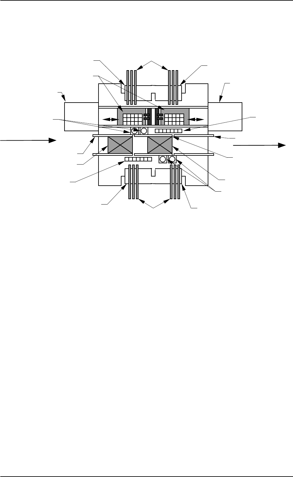
Fig. 1.14 P.C.B. Flow (From Left to Right)
6. Outline of System Operation
0004-002 1-38 Tg0246-PM-OP
6. Outline of System Operation
6.1 Perspective
(1) The P.C.B. sent to L conveyer is transferred from the input machine to the
standby position in Fig. 1.14.
(2) The P.C.B. at the standby position is transferred to the P.C.B. positioning
section and positioned there after the component-placed P.C.B. at the P.C.B.
positioning section is sent to the R conveyor.
Multi-Layer Tray Feeder L
(Option)
Multi-Layer Tray Feeder R
(Option)
Feeder Base #1
Feeder Base #2
Tape Feeder (Vibratory Stick Feeder)
Feeder Base #4
Feeder Base #3
Ta
p
e Feeder
Nozzle Stocker
Component Recognition Camera
Nozzle Stocker
Component
Recognition Camera
Tray Palette
R Conveyor
P.C.B. Positioning Section
L Conveyor
Standby Position
P Conveyor
(P.C.B. Positioning
Section)
(Front Side of Machine)
P.C.B. Flow Direction
(Input Machine)
(Output Machine)

(3) The deviation of the positioned P.C.B. is detected by the P.E.C. recogni-
tion function and the machine performs component pick-up and place-
ment operation according to the programmed data (pattern program).
The machine performs component pick-up and placement operations in
the following order.
Case: Setting of Recognition before Component Pick-Up
(3.1) P.E.C. Recognition (Placement Position)
(3.2) Nozzle Change
(3.3) Component Picks from Feeder
(3.4) Component Recognition
When the result is “OK”, the system proceeds to (3.5).
When the result is “NG (No Good)”, the component is dis-
charged.
(3.5) Component Placement
The cycle of (3.2) through (3.5) is repeated alternately on both
A and B beams.
Case: Setting of Recognition after Component Pick-Up
(3.1) Nozzle Change
(3.2) Component Pick from Feeder
(3.3) Component Recognition
When the result is “OK”, the system proceeds to (3.4).
When the result is “NG (No Good)”, the component is dis-
charged.
(3.4) P.C.B. Recognition (Placement Position)
(3.5) Component Placement
The cycle of (3.2) through (3.4) is repeated alternately on both
A and B beams.
(4) The component-placed P.C.B. sent to the R conveyor is transferred to the
output machine by the R conveyor.
6. Outline of System Operation
0004-002 1-39 Tg0246-PM-OP