1OM-1064-002.pdf - 第187页
4. SEMI-AUTOMA TIC OPERA TION *5 [P .C.B. LOCA TION [MOVE]] Key When this key is selected and the [MOVE] button is pressed, the P .C.B. located on the P .C.B. positioning section can be re-positioned. *6 [FULL AUTO CONT …
4. SEMI-AUTOMATIC OPERATION
*1
*8
*2
*5
*6
*3
*4
*7
*10
*9
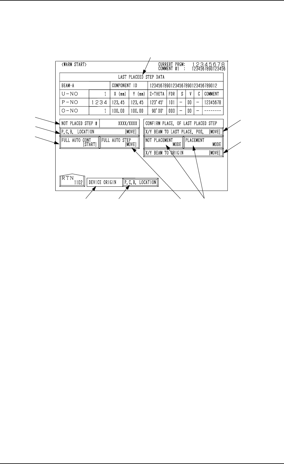
4.3 Warm Start
When the [WARM START] key is pressed at the “SEMI-AUTOMATIC OP-
ERATION” display, the following display appears on the screen.
9910-001 3-17 Tg0246-PM-OP
Fig. 3.5
*1 LAST PLACED STEP DATA
Shown under this label is the step data related to the component which
was placed last on the P.C.B.
*2 NOT PLACED STEP #
Shown in the text box is the number of steps for which components are
not placed. ({{/XX)
{{ : Number of steps for which components are not placed (the num-
ber of steps for which components are to be placed after the warm
start operation)
XX : Total Number of Pattern Program Steps
*3 DEVICE ORIGIN
This indicates whether or not the devices are zeroed.
• Label Color Coding
Devices at Origins: Green
Devices Not at Origins: Light Red
*4 [P.C.B. LOCATION] Key
This display section indicates how the P.C.B. is positioned.
When a P.C.B. is correctly positioned, this key turns green.
When there is no P.C.B. or a P.C.B. is not positioned correctly, this key
turns light red.
When the [P.C.B. LOCATION] key is pressed, the “MANUAL TRANS-
FER OPERATION” display appears on the screen.
Refer to “8. Manual Transfer Operation of Section 4” for details.
When *3 and *4 are green, it indicates that the P.C.B. positioning opera-
tion is set ready.

4. SEMI-AUTOMATIC OPERATION
*5 [P.C.B. LOCATION [MOVE]] Key
When this key is selected and the [MOVE] button is pressed, the P.C.B.
located on the P.C.B. positioning section can be re-positioned.
*6 [FULL AUTO CONT [START]] Key
When this key is selected and the [START] button on the operation panel
is pressed, the warm start function is activated.
Ref.: The “AUTO OPN MODE (PLACEMENT)” display appears after
the warm start function is activated.
*7 [FULL AUTO STEP [MOVE]] Key
When this key is selected and the [MOVE] button is pressed, the warm
start function is activated.
Ref.: The “AUTO OPN MODE (PLACEMENT)” display appears after
the warm start function is activated.
*8 [X/Y BEAM TO LAST PLACE. POS. [MOVE]] Key
When this key is selected and the [MOVE] button is pressed, the X/Y
beam moves such that the last placement step position is located at the
P.E.C. camera position, enabling to check how the last component is placed.
After the checking, zero the X/Y beam.
*9 [NOT PLACEMENT MODE] and [PLACEMENT MODE] Keys
[NOT PLACEMENT MODE] Key : Select this key when a component
is placed at the last placement step
position.
[PLACEMENT MODE] Key : Select this key when no component is
placed at the last placement step position.
Default: “NOT PLACEMENT MODE”
*10 [X/Y BEAM TO ORIGIN [MOVE]] Key
When this key is selected and the [MOVE] button on the operation panel
is pressed, the X/Y beam is moved back to its origin.
Ref. : When the warm start function starts, the “AUTO OPN MODE (PLACE-
MENT)” display appears on the screen and the machine starts placing
components on the P.C.B.
After components are placed, the subsequent P.C.B. is transferred and
the normal automatic operation starts.
Notes: (a) Component placement data is managed for each individual steps.
However, when no component missing data exists, the warm start
function cannot be activated.
(b) When the warm start function starts, the components picked up
by the nozzles are discarded into the component storage box.
(c) The machine does not implement the B.B.R. function (option).
(d) The P.E.C. recognition is re-performed.
(e) Before activating the warm start function, check that any
unrequired components, etc., are not scattered over the unfinished
P.C.B.
When the last component (component placed last) is placed up-
right or bent, remove it and select the [PLACEMENT MODE]
key *9 at the “WARM START” display to place a component at
the last placement step position.
(f) When the current pattern program data is changed with the “Warm
Start” function feasible, the computer system cannot be re-started
without actually turning the computer off and on.
9910-001 3-18 Tg0246-PM-OP
5. Operation Mode
*1
*2
*3
*4
*5
*6
5. Operation Mode
• Basically parameters for operation mode are set in the current pattern pro-
gram data. When some of the parameters (feeder alternate cancel, etc.) must
be modified according to situational changes and the required menu key is
pressed at the “OPERATION MODE” display, the corresponding display
opens, enabling the alteration of parameters set in the data boxes labeled
such as “RECOVERY MODE” (reserved function), etc.
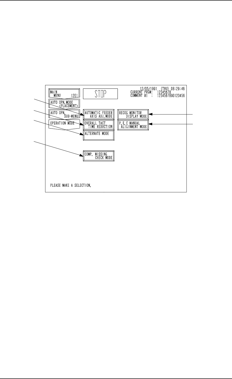
When the [OPERATION MODE] key is pressed at the “AUTO OPN. SUB-
MENU” display, the following display appears on the screen.
Fig. 3.6
*1 [AUTOMATIC FEEDER AXIS ADJ. MODE] Key
“ENABLE” or “DISABLE” can be set in the “AUTOMATIC FEEDER
AXIS SETTING (X) DIR.” and “AUTOMATIC FEEDER AXIS SETTING
(Y) DIR.” data boxes. The function to learn and follow up the feeder (B)
offset using statistical processing can be set to correct positional deviation
of component picks caused due to variations in feeders.
*2 [OVERALL TACT TIME REDUCTION] Key
This key enables the setting of upper limit of the overall tact time (covering
the operation speed of each device for coordination) specified in the com-
ponent library data.
*3 [RECOG MONITOR DISPLAY MODE] Key
When this key is pressed, the “RECOG MONITOR DISPLAY MODE”
display appears on the screen, enabling the selection of how to display the
results of recognition such as P.E.C. and component recognition functions.
*4 [P.E.C. MANUAL ALIGNMENT MODE] Key
When this key is pressed, the “P.E.C. MANUAL ALIGNMENT MODE”
display appears on the screen, enabling the designation of the manual align-
ment mode to cope with a P.E.C. recognition error.
*5 [ALTERNATE MODE] Key
When this key is pressed, the “ALTERNATE MODE” display appears on
the screen, enabling the operator to determine whether or not the alternate
feeder mode should be used.
*6 [COMP. MISSING CHECK MODE] Key
When this key is pressed, the “COMPONENT MISSING CHECK MODE”
display appears on the screen, enabling the operator to determine whether
or not the component missing check mode should be used.
9910-001 3-19 Tg0246-PM-OP