1OM-1064-002.pdf - 第239页
9.3 Procedure for Nozzle Storage (1) Select the [NOZ. RESET [MOVE]] key C. (2) Press the [HEAD #1] or the [HEAD #2] key G beside the label “BEAM A” or “BEAM B” to select a head. (3) Press the [MOVE] button. The machine s…
9. Manual Nozzle Change Operation
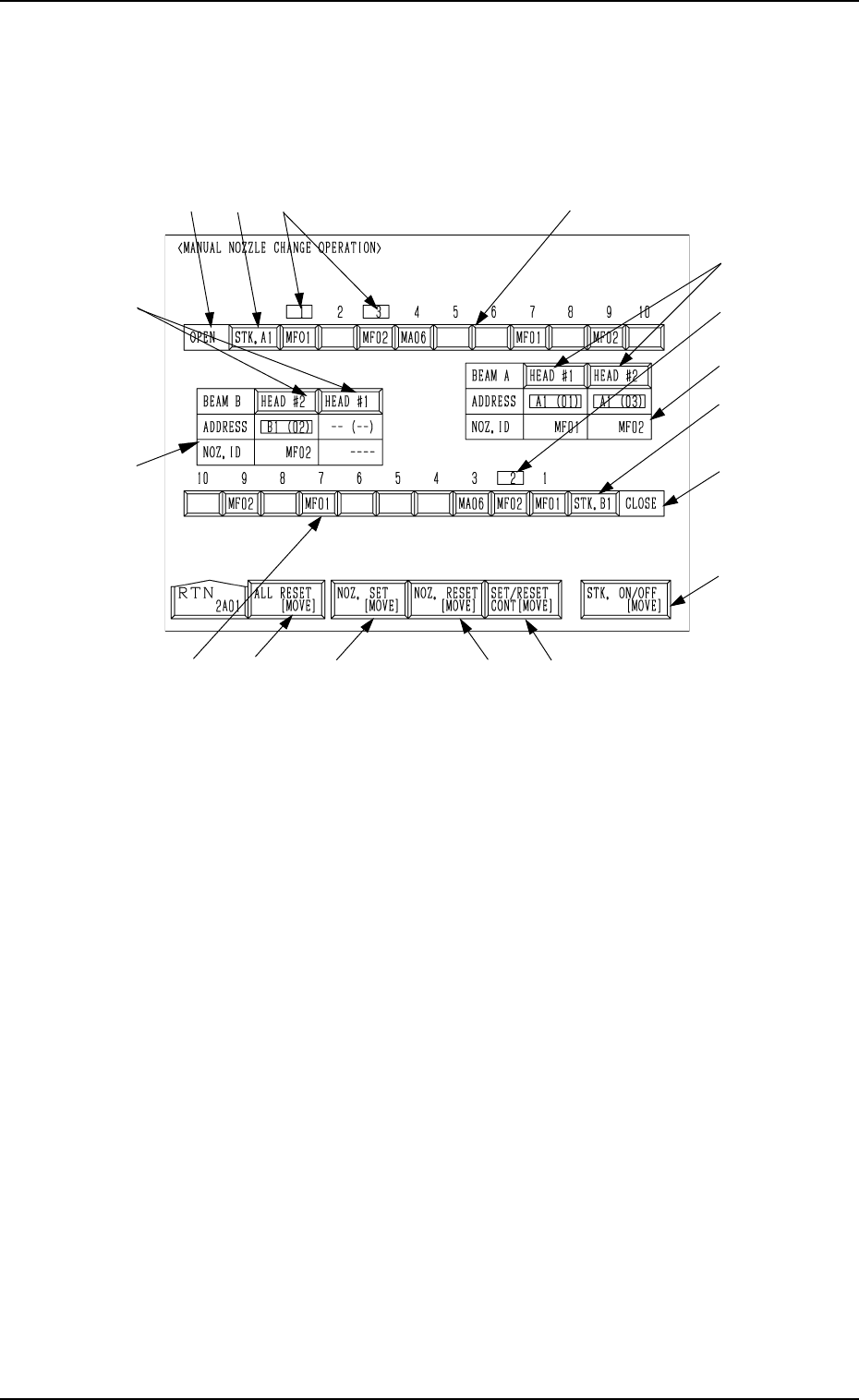
When the [MANUAL NOZZLE CHANGE OPERATION] key is pressed at
the “MANUAL MODE” display, the following display appears on the screen.
This display enables the cycle movement for opening or closing the nozzle
stocker and attaching or storing a vacuum nozzle through manual operations.
0103-003 4-22 Tg0246-PM-OP
9. Manual Nozzle Change Operation
Fig. 4.12
When the colour of Nozzle ID is white and the background color is red, it
means that the nozzle stocker is set to be bypassed.
Note: When set to be bypassed, the nozzle stocker cannot be used.
9.1 Procedure for Nozzle Stocker Opening/Closing
Operation
(1) Select the [STK. ON/OFF [MOVE]] key A .
(2) Press the [STK. A1] or the [STK. B1] key E to select the desired stocker.
(3) When the [MOVE] button is pressed, the specified nozzle stocker is opened
or closed.
It is indicated in F of the selected stocker whether the selected stocker is
open or closed.
9.2 Procedure for Nozzle Attachment
(1) Select the [NOZ. SET [MOVE]] key B.
(2) Press the [HEAD #1] or the [HEAD #2] key G beside the label “BEAM
A” or “BEAM B” to select a head.
(3) Press one of the nozzle ID keys H to select a nozzle to be taken out of the
nozzle stocker and attached.
(4) Press the [MOVE] button. The machine starts to attach the specified
nozzle.
(5) Shown in I are the IDs and the nozzle stocker addresses of the attached
nozzles.
Note: When the nozzle has already been attached to the head, this operation
cannot be performed.
I
G
D
B
C
F
E
A
J
I
G
H
HFEJ
K

9.3 Procedure for Nozzle Storage
(1) Select the [NOZ. RESET [MOVE]] key C.
(2) Press the [HEAD #1] or the [HEAD #2] key G beside the label “BEAM
A” or “BEAM B” to select a head.
(3) Press the [MOVE] button. The machine starts to store the nozzle on the
specified head in the nozzle stocker.
9.4 Procedure for Nozzle Batch Storage
(1) Select the [ALL RESET [MOVE]] key K.
(2) When the [MOVE] button is pressed, all nozzles on the heads are stored
in the nozzle stocker.
9.5 Procedure for Continuous Operation (Test on
Nozzle Attachment and Storage Operations)
(1) Select the [SET/RESET CONT [MOVE]] key D.
(2) Press the [HEAD #1] or the [HEAD #2] key G beside the label “BEAM
A” or “BEAM B” to select a head.
(3) When no nozzle is attached to the head, select a nozzle to be taken out of
the nozzle stocker and attached by pressing one of the nozzle ID keys H.
(4) Press the [MOVE] button. The machine performs a series of operation to
attach and store the nozzles for the specified head.
• When a nozzle has already been attached to the head, the machine
stores the nozzle in the nozzle stocker and performs the nozzle attach-
ment operation again.
• When no nozzle is attached to the head, the machine performs the
nozzle attachment operation and then stores the nozzle in the nozzle
stocker.
Ref.: (a) Only the nozzles from the nozzle stocker on Side A can be
attached to the beam-A head.
Only the nozzles from the nozzle stocker on Side B can be
attached to the beam-B head.
(b) The background color of the nozzle address J changes de-
pending on which head a vacuum nozzle is attached to.
A1 Head: Yellow
A2 Head: Light Green
B1 Head: Cyan
B2 head: Light Magenta
(c) The character color of the displayed nozzle ID changes de-
pending on how the nozzle ID is used.
Green : The nozzle ID is used in the current program.
Yellow: The nozzle ID is used in a pattern program other
than the current one.
White : Although the nozzle ID is not used in any pattern
program, it is registered in the component library.
When the nozzle is set to be bypassed, a red back-
ground color is shown.
Gray : The nozzle ID is not used in any pattern program.
It is not also registered in the component library.
0103-003 4-23 Tg0246-PM-OP
9. Manual Nozzle Change Operation
9. Manual Nozzle Change Operation
Rewriting Operation of Backup Memory
• The backup memory is used to manage which nozzles are attached to which
heads.
• The actual condition of the nozzle attachment may not match the condition
(information) stored in the backup memory in the handling, etc., after an
error has occurred in nozzle attachment or storage operation. When the ma-
chine is operated under such condition, trouble (collision, wrong placement,
etc.) will result. Therefore, it is required to rewrite the data stored in the
backup memory.
CAUTION
When the backup memory is rewritten by mis-
take, a possible source of trouble will be cre-
ated.
Special care and verification are required while
the data is being rewritten.
Only the person in charge of rewriting should
perform the rewriting operation.
Procedure for Rewriting Operation
(1) Open the “MANUAL NOZZLE CHANGE OPERATION” display (Fig.
4.12) to check how the nozzles are attached and how the data is stored in
the backup memory.
• When the actual condition of the nozzle attachment matches the condi-
tion (data) stored in the backup memory, it is not necessary to rewrite
the data.
• When the actual condition does not match the data stored in the backup
memory, proceed to Step (2).
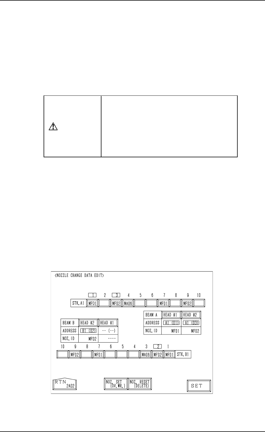
(2) When the “MANUAL NOZZLE CHANGE OPERATION” display (Fig.
4.12) is active and the [RESET] and [STOP] buttons are pressed at the
same time, the following display (hidden one) appears on the screen.
Fig. 4.13
9910-001 4-24 Tg0246-PM-OP