1OM-1064-002.pdf - 第131页
5. Preparation and Confirmation before Operation 5.2 Program Change Operation 5.2.1 Selection of Current Pattern Program (Program Change) • Set the current pattern program at the “PROGRAM CHANGE” display . (Hierarchical …

5. Preparation and Confirmation before Operation
(5) Check the line letter and the device number located at the bottom right of
the “MAIN MENU” display before starting data communication.
(6) Start sending data.
Refer to the instruction manual of the programming device for details on
how to transmit data.
Notes: (a) When the pattern program is transferred from the program-
ming device to the machine, the component library data speci-
fied in the pattern program is also sent out to the machine
simultaneously.
When the component library data having the same compo-
nent ID already exists in the machine, the specified compo-
nent library data is not sent out to the machine.
The floppy disk drive (FDD) of the machine is a reserved
function. In normal cases, it is not used to register pattern
programs.
(b) The requirements for data communication are as follows.
• The number of pattern programs stored in memory of the
machine should be “24 programs (models)” or less.
The total number of steps in a pattern program should be
“7,600 steps” or less.
• No data communication is available during editing of a
pattern program.
• No data communication is available during memory check
operation.
• No data communication is available when the [OPERA-
TION/SET UP] switch is set to the “SET UP” side.
9910-001 2-32 Tg0246-PM-OP
5. Preparation and Confirmation before Operation
5.2 Program Change Operation
5.2.1 Selection of Current Pattern Program (Program Change)
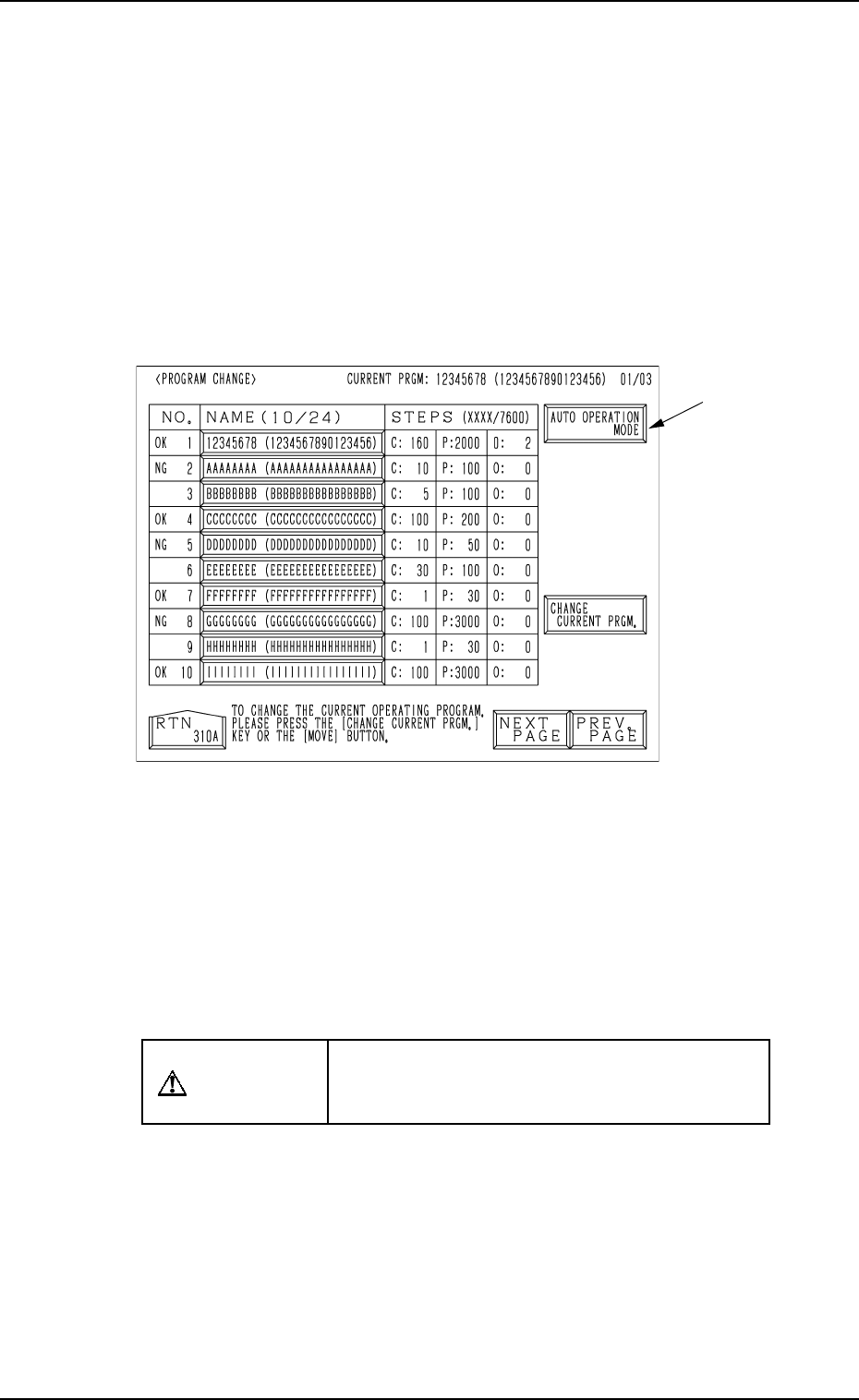
• Set the current pattern program at the “PROGRAM CHANGE” display.
(Hierarchical Sequence: “AUTO OPN. MODE <PLACEMENT>” Display
→ “AUTO OPN. SUB-MENU” Display → “PROGRAM CHANGE” Display)
This display can be opened from the “MANUAL MODE” display. (Hierarchi-
cal Sequence: “MAIN MENU” Display → “MANUAL MODE” Display)
Note: The menu operations are possible only when the machine is set in the
“STOP” mode.
0004-002 2-33 Tg0246-PM-OP
Fig. 2.21
Ref.: When the [AUTO OPERATION MODE] key A is pressed, the “AUTO
OPN MODE (PLACEMENT)” display opens directly.
Operation Procedure
(1) Set the [OPERATION/SET UP] switch to the “SET UP” side.
(2) Open the maintenance/supply cover and remove the P.C.B. support pins.
CAUTION
Power is kept “ON”! Perform the adjustment
carefully, protecting your hands from moving
mechanisms.
(3) Close the maintenance/supply cover and set the [OPERATION/SET UP]
switch to the “OPERATION” side.
(4) Open the “AUTO OPN. MODE <PLACEMENT>” display and check
the origin marks “”.
(5) Check that “” appears before all devices except “INPUT MACHINE”.
• If “” does not appear before all devices expect “INPUT MACHINE”,
proceed to Step (6).
• If “” appears before all devices expect “INPUT MACHINE”, pro-
ceed to Step (7).
A
5. Preparation and Confirmation before Operation
(6) Perform the zeroing operation.
(Refer to “5. Zeroing Operation of Section 4” for details.)
(7) Open the “PROGRAM CHANGE” display and select the pattern pro-
gram to be set as a current one by pressing the corresponding “NAME
(XX/XX)” key.
• The background color of the selected key turns blue.
(8) Press the [MOVE] button or the [CHANGE CURRENT PRGM.] key.
• When the [MOVE] button is pressed, proceed to Step (9).
• When the [CHANGE CURRENT PRGM.] key is pressed, proceed to
Step (10).
Ref.: When the [CHANGE CURRENT PRGM.] key is pressed, the con-
veyor width is not set up automatically.
It is required to separately set up the conveyor width.
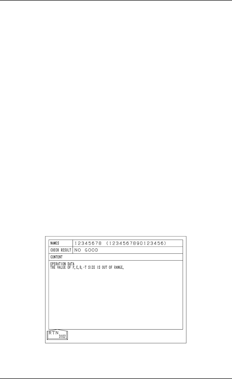
(9) When the [MOVE] button is pressed, the program check operation is
performed.
When the program is checked “OK”,
the conveyor width is set up (when “ON” is set in the “CONVEYOR
WIDTH” data box at the “SET-UP DATA” display) and the background
color of the program name turns green. (Hierarchical Sequence: “PAT-
TERN PROGRAM” Display → “SET-UP DATA” Display)
(When the background color of the program name turns green, it indi-
cates that the pattern program is set as a current one.)
When the program is checked “NO GOOD”,
The program change operation is not performed and the program check
display like one shown in Fig. 2.22 appears on the screen, showing the
contents of the error (s).
(“????????” appears when the current program is indefinite.)
Refer to the contents of the error and correct the pattern program data.
Then, perform the program change operation again by pressing the
[MOVE] button.
Fig. 2.22
9910-001 2-34 Tg0246-PM-OP