1OM-1064-002.pdf - 第209页
6. RECOVERY OPN. TEACHING OPN. Display Fig. 3.21 (4) Select the [SA VE] or the [DON’T SA VE] key . When the [SA VE] key is pressed, the changed component carriage data is saved and the “COMPONENT CARRIAGE DA T A EDIT” di…

6. RECOVERY OPN. TEACHING OPN. Display
*8 [PICK-UP LEVEL] Key
When a fine adjustment of the pick-up level is required before and after
the level is changed and a slight difference is found in component thick-
ness, this key can be used to change the data for stable component picks.
Pressing this key makes it possible to change the numerical values.
*9 [PLACEMENT LEVEL] Key
When there is a slight difference between the original component thick-
ness (unchanged thickness) and the changed one, this key can be used to
change the data for stable component placement.
Pressing this key makes it possible to change the numerical values.
*10 [++] and [+] Keys
These keys can be used to increase the values in the “PICK-UP LEVEL”
or the "PLACEMENT LEVEL" data field.
[++] Key: Press this key to increase the selected value in the incre-
ments of 0.1 mm.
[+] Key : Press this key to increase the selected value in the incre-
ments of 0.01 mm.
*11 [-] and [- -] Keys
These keys can be used to decrease the values in the “PICK-UP LEVEL”
or the “PLACEMENT LEVEL” data field.
[- -] Key : Press this key to decrease the selected value in the incre-
ments of 0.1 mm.
[-] Key : Press this key to decrease the selected value in the incre-
ments of 0.01 mm.
• When the parameters (direction, type, component detection, automatic feeder
axis adjustment, pick-up level, and placement level) are different from those
defined in the component library data, the background color of the perti-
nent text fields turns red.
“-” appears beside the feeder Nos. (FDR-NO).
• The feeder slot Nos. (FDR-NO) can be selected only within the same
(shared) carriage.
To move to another carriage, select the [A (40)] or the [B (0)] key.
Operation Procedure
(1) Move the line cursor to the feeder slot No. (FDR-NO) where components
different from those (the components having the corresponding IDs) de-
fined in the component library data are supplied.
(2) Press the [TYPE], the [DIR.], the [COMP. MISSING [SENSOR]], the
[X] and [Y] of “AUTO. FDR. AXIS ADJ.”, the [PICK-UP LEVEL], or
the [PLACEMENT LEVEL] key and edit each corresponding parameter.
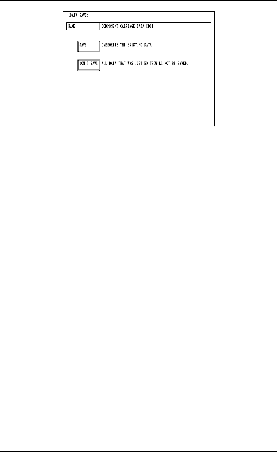
(3) When the [RTN] key is pressed, the following display appears on the
screen.
9910-001 3-39 Tg0246-PM-OP
6. RECOVERY OPN. TEACHING OPN. Display
Fig. 3.21
(4) Select the [SAVE] or the [DON’T SAVE] key.
When the [SAVE] key is pressed, the changed component carriage data is
saved and the “COMPONENT CARRIAGE DATA EDIT” display (Fig.
3.19) appears on the screen.
When the [DON’T SAVE] key is pressed, the changed component car-
riage data is not saved.
Notes: (a) Parameters can be changed only when the control command “-”
or “E” is set with the machine in the “STOP” or the “PAUSE”
mode.
(b) The component carriage parameters (packaging change data) are
updated (cleared) after a program change operation is performed.
When the feeder Nos. match the slot Nos. of the actually allo-
cated feeders perfectly before and after the program change op-
eration is performed, the component carriage parameters are
backed up (succeeded).
9910-001 3-40 Tg0246-PM-OP
6. RECOVERY OPN. TEACHING OPN. Display
9910-001 3-41 Tg0246-PM-OP
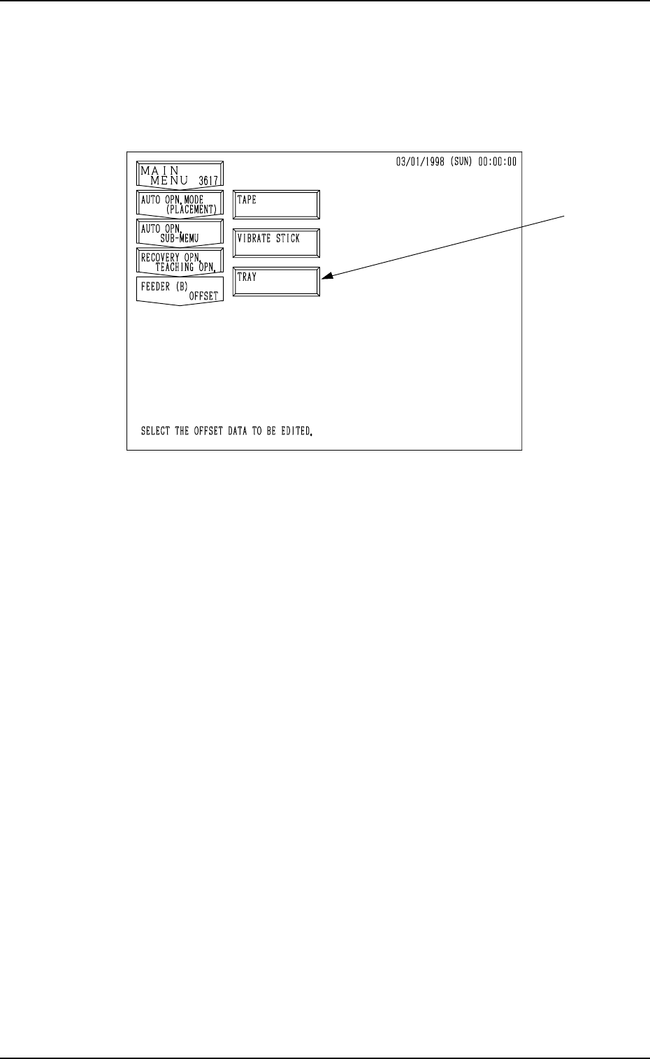
6.4 FEEDER (B) OFFSET Display
When the [FEEDER (B) OFFSET] key is pressed at the “RECOVERY OPN.
TEACHING OPN.” display, the following display appears on the screen.
Note: The -marked item is optional.
Fig. 3.22
The feeder (B) offset data is used to correct the positional deviation in compo-
nent pick-up positions caused due to the variation in feeders.
Refer to “5.2.5 FEEDER (B) OFFSET Display of Section 2” for details.