1OM-1064-002.pdf - 第135页
5. Preparation and Confirmation before Operation 5.2.2.2 Setting Procedure of P .C.B. Support Pins T o set up the P .C.B. support pins at the “PCB SUPPORT PINS SET-UP MODE” display • Refer to “10. P .C.B. Support Pins Se…
5. Preparation and Confirmation before Operation
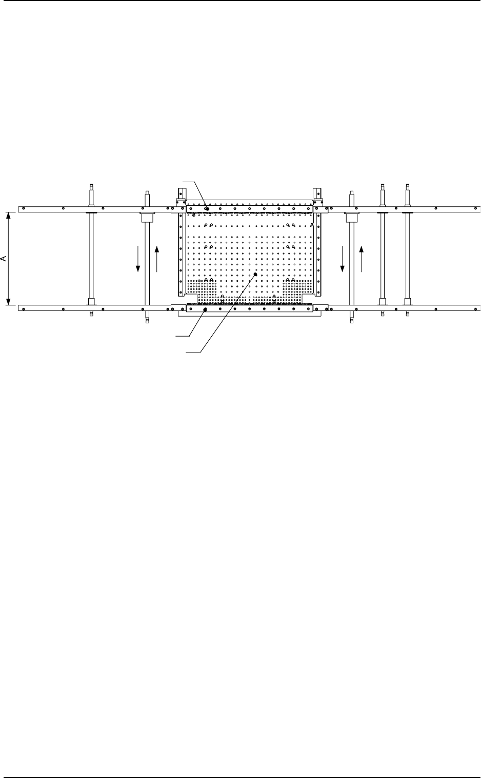
Movable Chute
Fixed Chute
P.C.B. Positioning Section (P Conveyor)
5.2.2 Adjustment of P.C.B. Positioning Section
5.2.2.1 Adjustment of Conveyor Width
(1) Use the automatic set-up function to adjust Dimension A to “P.C.B.
Width + 0.5 mm (standard value)”.
In an actual case, the parameter set in the “CLEARANCE”data box
is used.
(2) Transfer P.C.B.’s through manual operation and check that they can
be conveyed smoothly without falling off.
0004-002 2-36 Tg0246-PM-OP
Fig. 2.23 View based on Reference Point "R-FRONT"
Notes: (a) Pay attention to the following points when the conveyor width
is automatically set up.
• When the conveyor width is zeroed, it is adjusted to “381 mm
(the largest P.C.B. size)”. Check that nothing around the con-
veyor touches part of the conveyor.
• Confirm that there is no P.C.B. on the conveyor.
Before the conveyor width set-up operation is initiated, each
conveyor is automatically activated to check that no P.C.B. is
located at any irregular position.
• Confirm that the P.C.B. support pins are removed.
(b) Fig. 2.23 shows the view based on Reference Point “R-FRONT”.
The same procedure applies regardless of a reference point.
5. Preparation and Confirmation before Operation
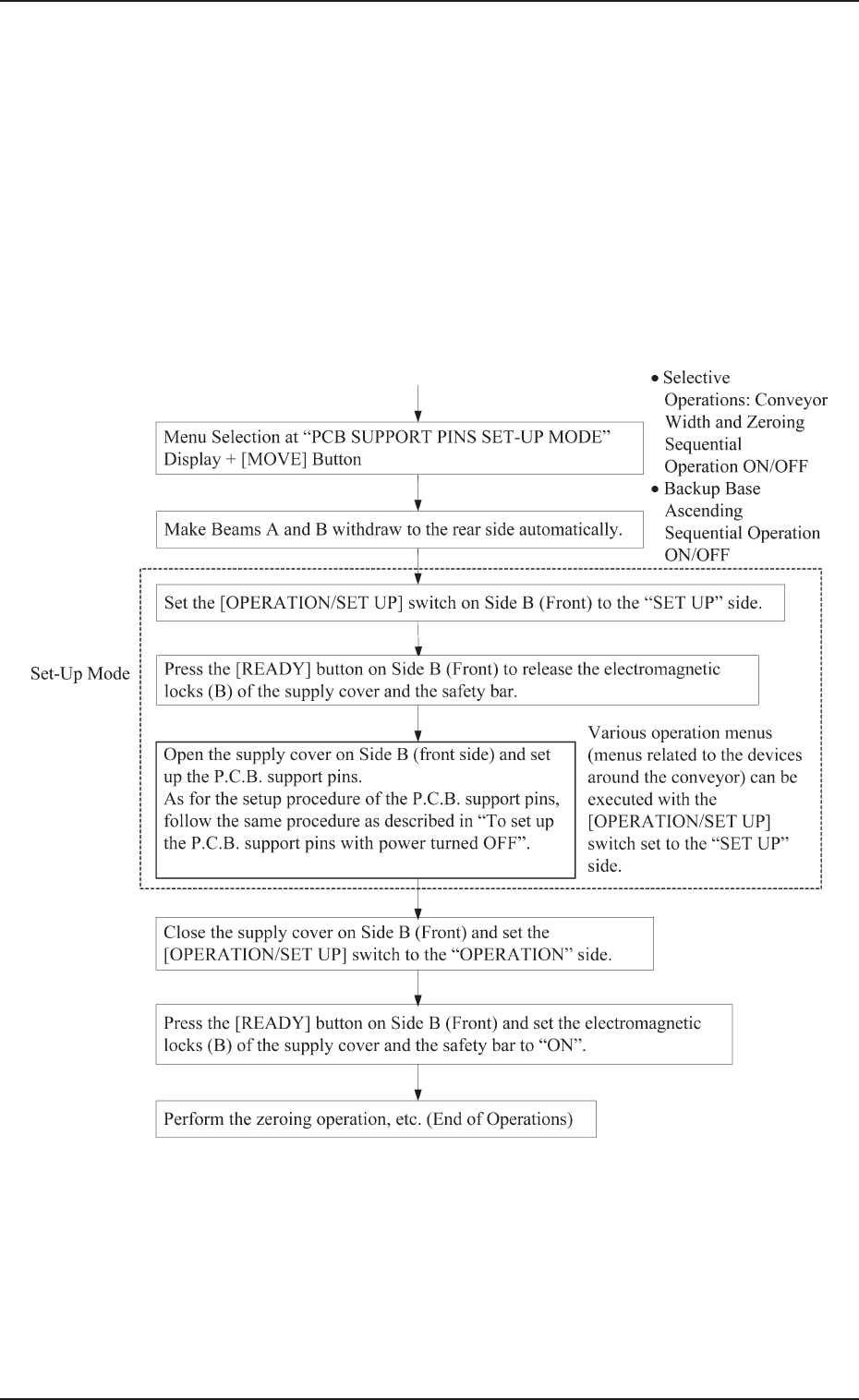
5.2.2.2 Setting Procedure of P.C.B. Support Pins
To set up the P.C.B. support pins at the “PCB SUPPORT PINS
SET-UP MODE” display
• Refer to “10. P.C.B. Support Pins Set-Up Mode of Section 4” for
details.
Starting Condition: • All devices must be zeroed.
• The maintenance/supply cover must be
closed.
• The LED of the [READY] button must be
“ON” (power supplied to the beam)
0004-002 2-37 Tg0246-PM-OP
5. Preparation and Confirmation before Operation
To set up the P.C.B. support pins with power turned OFF
CAUTION
The load power to the motor, etc. is shut off,
but the setting operation must be performed
carefully, protect your hands from moving
mechanism inside the machine.
The purpose for setting up the PCB support pins, is to hold the height of
the PCB upper surface at the proper position and to stabilize the machine.
(1) Check the condition of the P.C.B.’s to be handled.
(Check the size and thickness of the P.C.B.’s and whether or not com-
ponents are previously placed on the back.)
(2) Determine whether or not the set-up operation must be performed.
• When the set-up operation is not required (the same condition as
that of the current production can be applied), perform the pro-
gram change operation for the automatic operation.
• When the set-up operation is required (different condition from
that of the current production), proceed to Step (3).
(3) Stop the operation and set the power breaker to “OFF”.
CAUTION
To prevent the power breaker from being set
to “ON” by mistake, lock the power breaker us-
ing a padlock kept by the person in charge.
Follow the instructions described in “5.1 Power
Breaker Box of Section 1”.
(4) Open the supply cover and detach all feeders.
(5) Detach the safety bar on Beam B and open the maintenance cover.
Refer to “1.5 Opening and Closing of Supply Cover of Section 2”
and “1.6 Opening and Closing of Maintenance Cover of Section 2”
for details on how to open or close the covers and follow the instruc-
tions for safe operations.
(6) Move Beam B to the Beam A side by pushing.
(7) Remove the P.C.B. support pins.
Ref.: If the P.C.B. support pins are not removed, the movable chute
will collide with the pins during the set-up operation. (See
Fig. 2.24-3.)
(8) Check that a P.C.B. support pin, etc., is not left behind on the backup
table.
(9) Check that no component or dust, etc., has fallen into the holes on
the backup table.
(10) Close the maintenance cover and then the supply cover. After that,
attach the safety bar.
(11) Set the power breaker to “ON”.
(12) After zeroing, set up the conveyor width.
(Refer to “Section 4 Manual Mode Menus” for details.)
(13) Follow the procedure similar to Step (3) and turn off the power.
(14) Detach the safety bar on the Beam B side, open the supply cover, and
then the maintenance cover.
(15) Move Beam B to the Beam A side by pushing.
(16) Insert the P.C.B. support pins vertically into the holes on the PCB
backup table. The pins are installed so that they are dispersed equally
over the P.C.B. to be supported.
0103-003 2-38 Tg0246-PM-OP