Programming_mail.pdf - 第101页
III- 27 Programming Manual Part III Inspection Algorithm 1.10.3 Setting Procedur e of Shift Inspection Step1: Select a lighting that displays a polarity visually clear from the Lighting drop-down list. Step2: Adjust the …
III-26
Programming Manual
Part III Inspection Algorithm
1.10 Diagonally
1.10.1 Inspection Overview
Diagonally is the algorithm to inspect the average luminance of the inspection windows which are
located on symmetrical positions from the center of component.
Diagonally is suitable for polarity inspection of IC components.
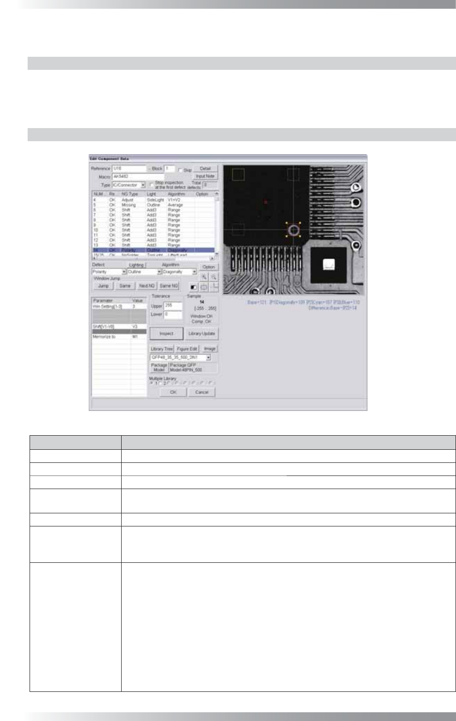
1.10.2 Parameter Setting
Figure 1-29 Diagonally
Parameter Description
Lighting Select a lighting that displays a polarity visually clear.
Algorithm Select Diagonally.
Win Setting[1-3] Set the number of the windows to be compared.
Shift[V1-V8]
Enter the appropriate vector. Any value from V1 to V8 is available.
Select the vector according to the Memorize to fi eld of the Adjust window.
Memorize to -
Upper, Lower
If brightness level of polarity is higher than brightness level of component body, enter 255
in the Upper fi eld and 1 in the Lower fi eld. If brightness level of polarity is lower than
brightness level of component body, enter -1 in the Upper fi eld and -255 in the Lower fi eld.
Sample
If 1 is entered in Win setting, the brightness level difference between the window
and the window on the point-symmetric point will be calculated and its result
becomes the sample value.
If 2 is entered, in addition to operations of 1, the brightness level difference between
the window and the window at the center point on the component will also be
calculated. Two brightness level difference values are compared and the bigger one
becomes the sample value.
If 3 is entered, in addition to operations of 1, the brightness level difference between
the window which the setting is applied and the window on the line-symmetric point
will be calculated. Three brightness level difference values are compared and the
biggest one becomes the sample value.
Table 1-8 Parameter of Diagonally
III-27
Programming Manual
Part III Inspection Algorithm
1.10.3 Setting Procedure of Shift Inspection
Step1: Select a lighting that displays a polarity visually clear from the Lighting drop-down list.
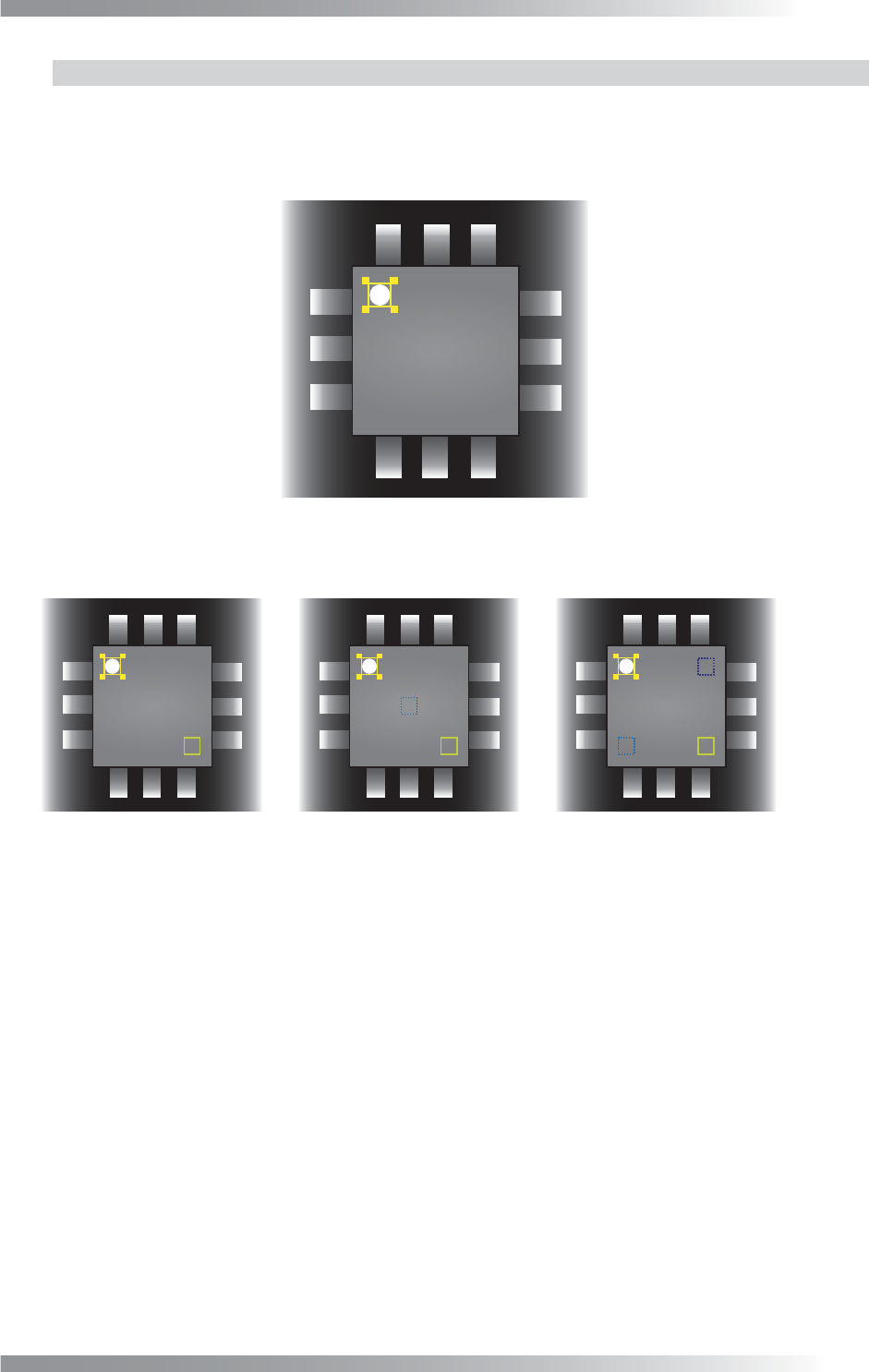
Step2: Adjust the Diagonally inspection window position to surround the polarity mark.
Figure 1-30 Inspection Window of Diagonally
Step3: Set the number of the windows to be compared in Win Setting.
㪧㪈 㪧㪈
㪧㪈
㪧㪉
㪧㪉
㪧㪊
(a) Win Setting 1 (b) Win Setting 2 (c) Win Setting 3
Sample value = Base - P1
Calculate Base - P1, Base - P2, and Base - P3.
Max value is sample value.
Calculate Base - P1 and Base - P2.
Max value is sample value.
㪙㪸㫊㪼 㪙㪸㫊㪼 㪙㪸㫊㪼
Figure 1-31 Win Setting
Step4: If the brightness level of the polarity mark is higher than the brightness level of the component
body, enter 255 in the Upper fi eld and 1 in the Lower fi eld. If the brightness level of the
polarity mark is lower than the brightness level of the component body, enter -1 in the
Upper fi eld and -255 in the Lower fi eld.
Step5: Enter the appropriate vector into the Shift fi eld by selecting from V1 to V8 according to the
vector used in Memorize to in the Adjust window.
Step6: Press Inspect. Make sure that the inspection is completed properly.
III-28
Programming Manual
Part III Inspection Algorithm
1.11 Black/White
1.11.1 Inspection Overview
Black/White is the algorithm to inspect the percentage of the specifi ed brightness level in the
inspection window.
If the percentage of the specifi ed level exceeds a certain value, the result will be OK.
Black/White is suitable for solder inspection of chip components.
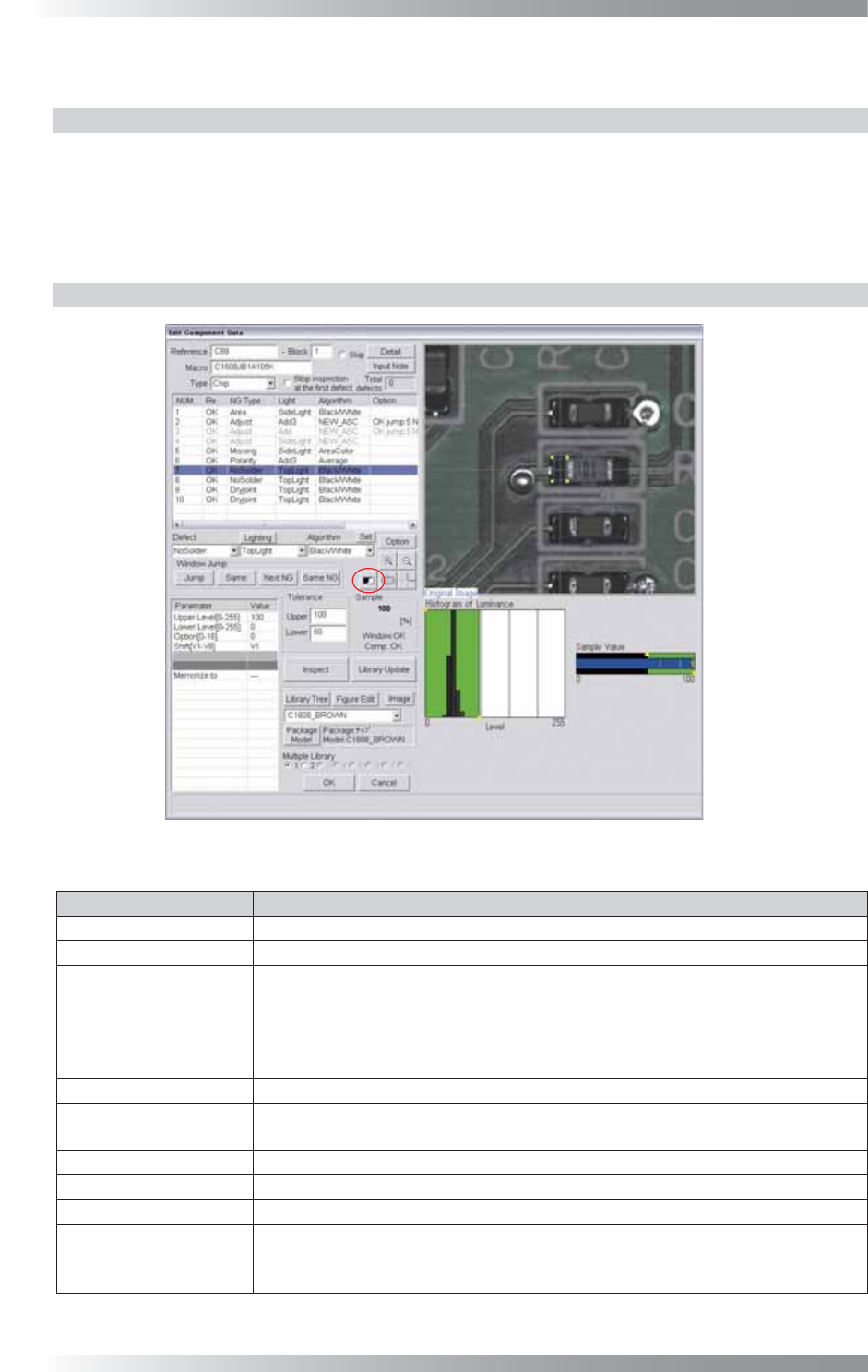
1.11.2 Parameter Setting
Figure 1-32 Black/White
Parameter Description
Lighting
Select TopLight to inspect solder paste.
Algorithm Select Black/White.
Upper Level[0-255],
Lower Level[0-255]
Calculates a value intermediate between OK sample value and NG sample
value. If OK sample value is smaller than NG sample value, enter intermediate
value in Upper Level fi eld and 0 in Lower Level fi eld. If NG sample value is
smaller than OK sample value, enter 255 in Upper Level fi eld and intermediate
value in Lower Level fi eld.
Option[0-16]
Enter 0.
Shift[V1-V8]
Set the OK range. The maximum value is 100 in Upper fi eld and minimum value
is 0 in Lower fi eld.
Memorize to -
Upper, Lower
Set OK range. The maximum value of Upper is 100 and minimum value of Lower is 0.
Sample
Shows the percentage of the specifi ed brightness level in the inspection window.
The graph in the lower
right side of the dialog
The Histogram of Luminance bar graph shows the number of pixels of every
bright level. Green area is the specifi ed area by Upper Level and Lower Level.
The sample Value shows upper limit and lower limit.
Table 1-12 Parameter of Black/White