Programming_mail.pdf - 第118页
III- 44 Programming Manual Part III Inspection Algorithm Step9: This is the parameter setting for lifted lead inspection. Lifted lead inspection has two steps. First inspection calculates average brightness level in pad …
III-43
Programming Manual
Part III Inspection Algorithm
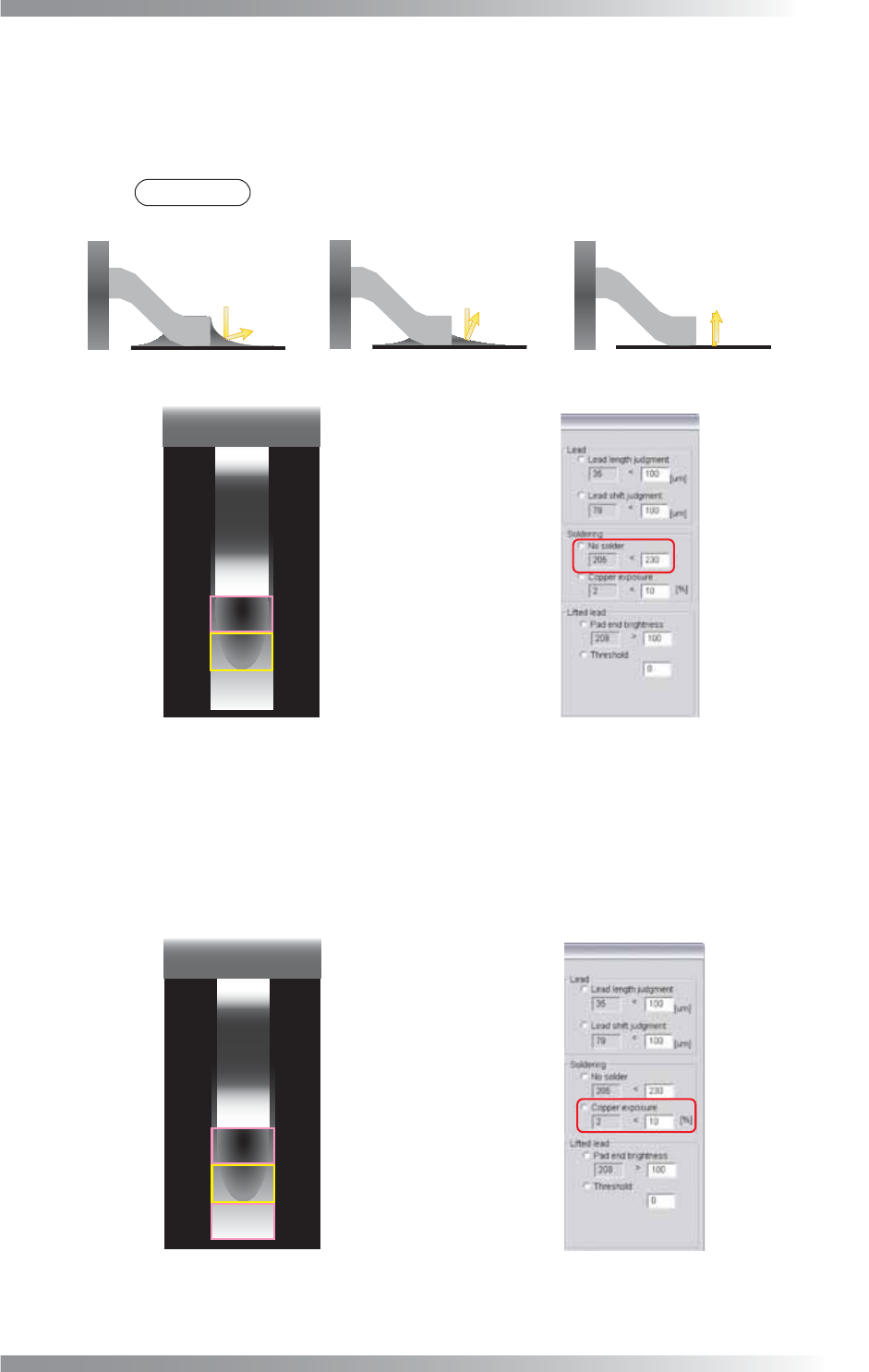
Step7: This is the parameter setting for solder inspection. It calculates average brightness level in
pad lead area and pad center area as sample value. If the sample value is lower than OK
range, the result will be OK.
Default is 230. If necessary, change the value according to inspection accuracy.
NOTE
The average brightness level is lower in case of no solder or insuffi cient solder.
(a) Normal
(b) Insufficient Solder
Low Brightness High Brightness
(c) No Solder
High Brightness
Pad Center Area
Pad Lead Area
Figure 1-48 Solder Inspection
Step8: This is the parameter setting for copper exposure inspection. It is useful to detect copper
area due to insuffi cient solder. It calculate the percentage of copper color defi ned as more
than 80% of hue and color saturation and more than 60% of brightness in pad lead, pad
center, and pad end area. If the sample value is lower than OK range, the result will be OK.
The default is 10%. If necessary, change the value according to the solder condition.
Pad Center Area
Pad Lead Area
Pad End Area
Figure 1-49 Copper Inspection
III-44
Programming Manual
Part III Inspection Algorithm
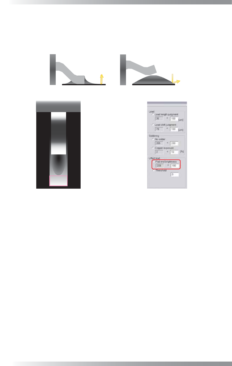
Step9: This is the parameter setting for lifted lead inspection. Lifted lead inspection has two steps.
First inspection calculates average brightness level in pad end area. If the sample value is
higher than OK range, the result will be OK. Default is 100. If necessary, change the value
according to the inspection accuracy. If the fi rst inspection is NG, the second inspection
shown in Step10 will be done.
(a) Normal
(b) LiftedLead
High Brightness
Low Brightness
Pad End Area
Figure 1-50 Lifted Lead Inspection 1
III-45
Programming Manual
Part III Inspection Algorithm
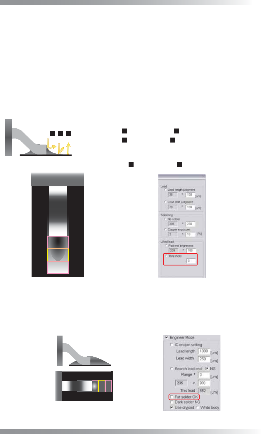
Step10: If the fi rst inspection shown in Step9 is NG, the second inspection will be done. The comparison
brightness level in pad lead, pad center, and pad end area will be shown as sample value. If
solder is in good condition, the brightness level is darker in pad lead area and brighter in pad
end area. This inspection is separated into two steps. The comparison of brightness level, the
brightness level in pad end area minus pad center area and the brightness level in pad
end area minus pad lead area, is shown as sample value in fi rst inspection. If the sample
value is larger than Threshold, the result will be OK (Default is 0). If either the brightness
level in pad end area minus pad center area or the brightness level in pad end area
minus pad lead area is NG, the second inspection, the brightness level in pad center area
minus pad lead area, will be done. If the sample value is larger than Threshold, the result
will be NG. If necessary, change the value according to the solder condition.
㪈
㪉
㪊
Pad Center Area
Pad Lead Area
Pad End Area
Pad End Area( ) - Pad Center Area( ) > Setting Value(Default is 0)
㪊
㪉
Pad End Area( ) - Pad Lead Area( ) > Setting Value(Default is 0)
㪊
㪈
㩿㪈㪀㩷Calculate following equation. If the result will be NG, proceed to (2).
㩿㪉㪀㩷Calculate following equation. If the result will be NG, judged as lifted lead.
Pad Center Area( ) - Pad Lead Area( ) > Setting Value(Default is 0)
㪉
㪈
Figure 1-51 Lifted Lead Inspection 2
Step11: If solder volume is extremely high, the brightness level in pad area is darker. In case to judge
high-volume-solder as OK, check Fat solder OK. If Fat solder OK is checked, the lifted lead
inspection is skipped. Also after copper exposure inspection, If the average brightness level
of pad lead, pad center and pad end area is lower than 100, the result will be OK.
Fat Solder
Figure 1-52 Fat solder OK