Programming_mail.pdf - 第203页
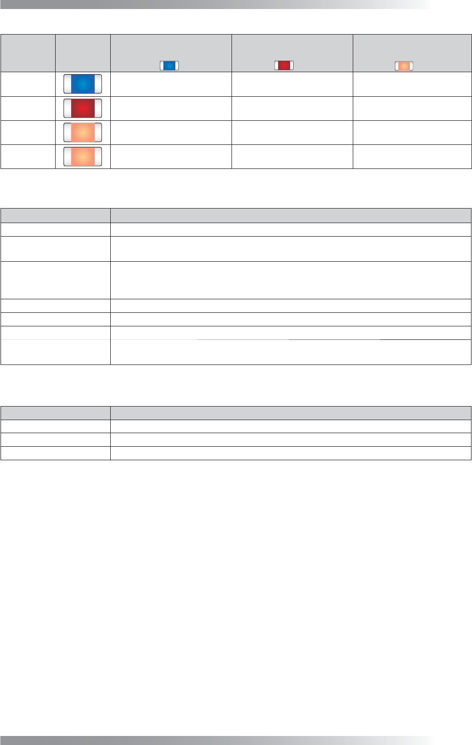
V- 13 Programming Manual Part V Other Function Component Name Component Color Inspection Result before Adjustment (Registered as OK color) Inspection Result after Adjustment 1 (Combine with OK color) Inspection Result af…
V-12
Programming Manual
Part V Other Function
1.3 Adjust KPK Data
1.3.1 KPK Debug
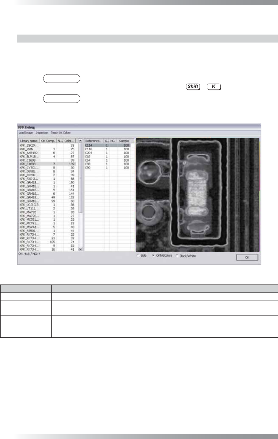
The KPK Debug dialog shown in Figure 1-17 appears after KPK data is extracted.
Adjust KPK inspection data. Double-click the component to open edit component dialog.
Refer to Part V 1.3.2 Edit Component Data Dialog.
NOTE
The same operation can be performed by selecting Edit > KPK Windows
Debugging from the menu-bar or pressing
+
.
NOTE
Select a component from the list-box and component image is displayed.
Magnifi cation percentage can be changed by scrolling wheel of mouse.
Figure 1-17 KPK Debug
Item Description
Load Image Opens images or switch images.
Inspection
Inspects opened images.
The inspection is automatically operated if the inspection data is changed.
Teach OK Colors
An OK component might be misjudged NG because of component color variation.
Combines the color which is misjudged as NG and the OK color to reduce the false call.
Select All NG components or Selected Library to fi nd the false call data.
Table 1-4 Menu-bar
V-13
Programming Manual
Part V Other Function
Component
Name
Component
Color
Inspection Result
before Adjustment
(Registered as OK color)
Inspection Result
after Adjustment 1
(Combine with OK color)
Inspection Result
after Adjustment 2
(Combine with OK color)
C1
OK OK OK
C2
NG (False Calls) OK OK
C3
NG (False Calls) NG (False Calls) OK
C4
NG (False Calls) NG (False Calls) OK
Table 1-5 The Example of Teach OK Colors
Item Description
Library Name
Library name.
OK Comp. / NG Comp.
Each numbers of the component OK/NG is displayed. If the inspection data is adjusted
properly, the result will be OK with OK PCB and the result will be NG with bare PCB.
Color distance
Extract two the most similar colors. One is from OK color, another is from NG color. The
distance of these two similar colors is displayed as a value. The smaller the value is, the
less color difference is between components and PCBs.
Reference Name
Component name.
Block number Sub board number.
NG
Displays NG when a component is judged as NG by KPK.
Sample
Sample values is the percentage of area which brightness level is over the specifi ed
value in the inspection window if the default algorithm Black/White is used.
Table 1-6 Each Item of Header
Item Description
Side
SideLight image is displayed.
OKNGColors
OKNGColors image is displayed.
Black/White
Monochrome image by algorithm Black/White is displayed.
Table 1-7 Select Lighting
V-14
Programming Manual
Part V Other Function
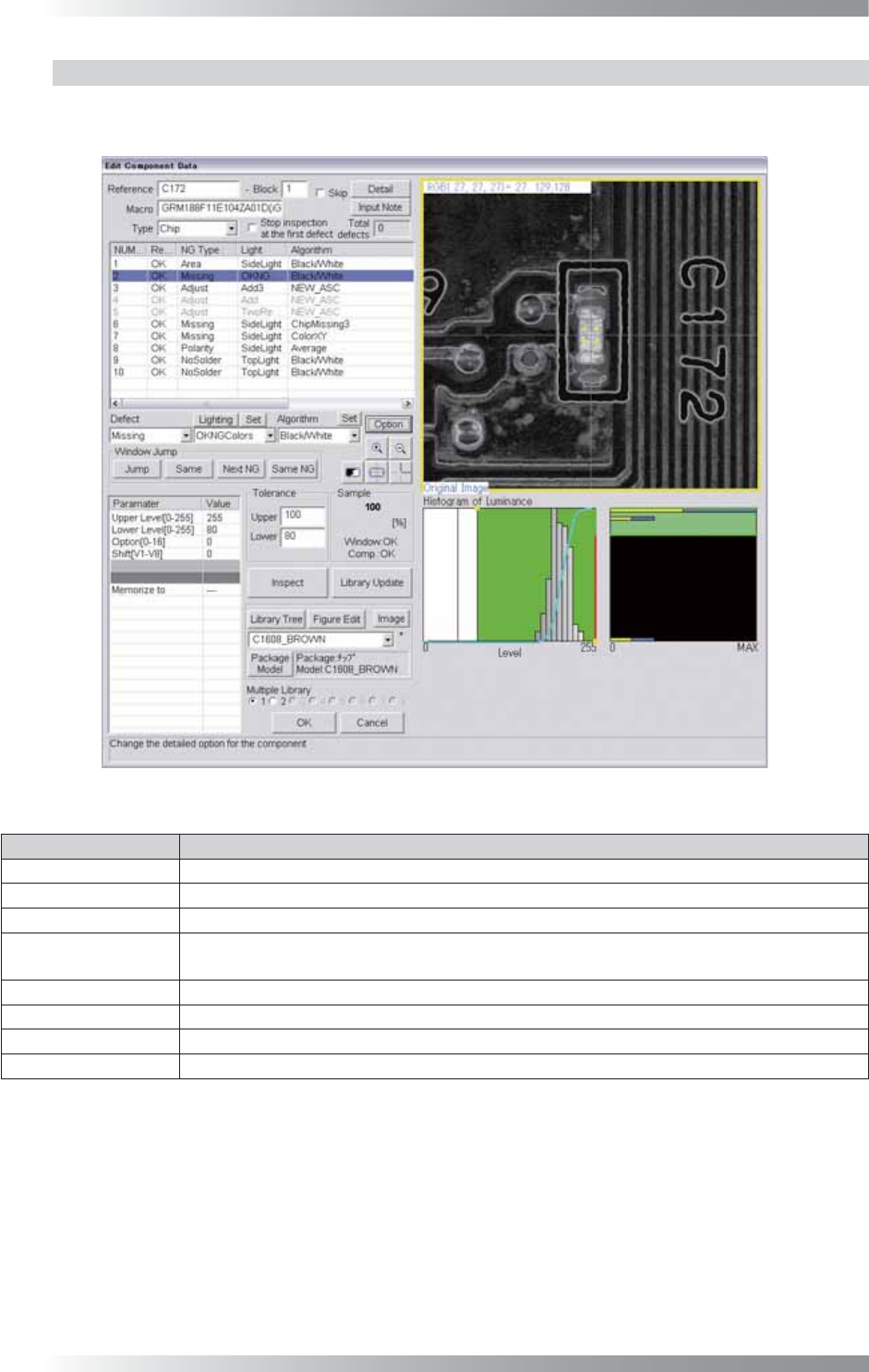
1.3.2 Edit Component Data Dialog
Double-click the component in KPK Debug dialog and the dialog shown in Figure 1-18 appears.
The second inspection window is KPK window.
Figure 1-18 KPK Window
Parameter Description
Defect Select Missing.
Lighting Select OKNGColors. Press Set in the right side of Lighting to set details.
Algorithm Select Black/White.
Upper Level[0-255],
Lower Level[0-255]
Upper Level is upper limit of brightness level. Lower Level is lower limit of brightness level.
Enter 255 in Upper Level fi eld. Press Set in the right side of Algorithm to adjust Lower Level.
Option[0-16] Enter 0.
Shift[V1-V8] Enter 0.
Memorize to -
Upper, Lower
Set the OK range. Enter 100 in Upper fi eld and arbitrarily value in Lower fi eld.
Table 1-8 Parameter of KPK