Programming_mail.pdf - 第136页
III- 62 Programming Manual Part III Inspection Algorithm 1.17 ImageMatchEx 1.17.1 Inspection Ov er view ImageMatchEx is the algorithm to inspect for pattern matching inspection. ImageMatchEx compares registered image and…
III-61
Programming Manual
Part III Inspection Algorithm
1.16.3 Setting Procedure
Step1: Select SideLight from the Lighting drop-down list.
NOTE
Change the lighting to LowLight, if fl ux is detected as bridge with SideLight.
Step2: Change the inspection window size to surround the area from the lead base to the pad end.
Align its width to the lead pitch.
Step3: Enter values in the Upper fi eld and the Lower fi eld.
NOTE
Standard values are 80 (Upper) and 0 (Lower).
Step4: Enter the appropriate vector into the Shift fi eld by selecting from V1 to V8 according to the
vector used in the Memorize to fi eld in the Adjust window.
Step5: Right-click on Distribution in the inspection item list and select Parameter Copy to copy
parameter to the other leads.
Step6: Lead pitch is adjusted automatically by pressing Jump in the upper left side of the dialog.
Step7: Press Inspect. Make sure that the inspection is completed properly.
㪉㪇
㪋㪇㪊㪇
㪌㪇 㪊㪇
㪋㪇
㪍㪇㪋㪇
㪌㪇㪌㪇
㪊㪇
㪋㪇
㪎㪇
㪌㪇
㪍㪇
㪌㪇
㪉㪊㪇㪍㪇
㪋㪇 㪍㪇
㪉㪉㪇
㪉㪇㪊㪇
㪊㪇㪌㪇
㪊㪇
㪎㪇
㪉㪈㪇
㪌㪇
㪋㪇
㪉㪇
㪊㪇㪍㪇
㪊㪇 㪋㪇
㪌㪇
㪌㪇㪉㪇㪇
㪍㪇㪋㪇
㪉㪉㪇
㪎㪇
㪊㪇
㪍㪇
㪌㪇
㪉㪇
㪋㪇 㪋㪇 㪈㪎㪇 㪋㪇 㪈㪐㪇 㪈㪐㪇 㪈㪐㪇 㪈㪏㪇
(a) Normal (c) Bridge
(b) Bleeding
(It is not bridge)
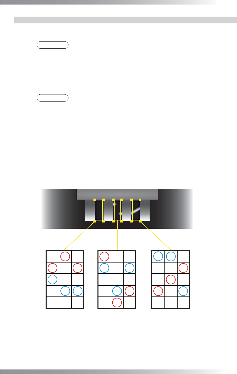
Divide inspection window into several blocks.
Calculate maximum brightness level minus minimum brightness level in each column.
Minimum value is sample value.
(Sample Value is higher)
Figure 1-76 Bridge Inspection by Distribution
III-62
Programming Manual
Part III Inspection Algorithm
1.17 ImageMatchEx
1.17.1 Inspection Overview
ImageMatchEx is the algorithm to inspect for pattern matching inspection.
ImageMatchEx compares registered image and actual image inside the inspection window and
calculate matching rate.
ImageMatchEx can be recognized not only alphanumeric character but also symbol.
ImageMatchEx is suitable for missing or miss-mounting of any components inspection.
NOTE
ImageMatchEx can be used for Adjust. This algorithm corrects the amount of
misalignment of CAD data with the actual position on the components.
1.17.2 Parameter Setting
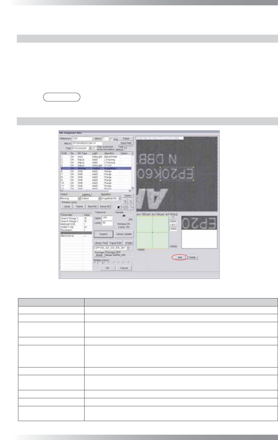
Figure 1-77 ImageMatchEx
Parameter Description
Lighting Select a lighting that displays characters visually clear.
Algorithm Select ImageMatchEx.
Search Range X,
Search Range Y
Set search range (=yellow dotted line). Enter the bigger value to enlarge the search
range. If the search range is not appropriate, the calculation time might be long.
Method[1/2/3]
Enter 1.
Shift[V1-V8]
Enter the appropriate vector. Any value from V1 to V8 is available.
Select the vector according to the Memorize to fi eld of the Adjust window.
If using ImageMatchEx for misalignment adjustment, enter 0.
Resolution Enter 1.
Memorize to
Enter V4 in Memorize to to refl ect this amount of misalignment to other
algorithm.
Upper, Lower
Set the upper and lower limit of the OK range.
Sample
Shows the match percentage.
The X and Y in the lower
right side of the dialog
Enter 99999.
If using ImageMatchEx for Adjust, enter the OK range in the X fi eld and Y fi eld.
Table 1-27 Parameter of ImageMatchEx
III-63
Programming Manual
Part III Inspection Algorithm
1.17.3 Setting Procedure
Step1: Select a lighting that displays the characters visually clear from the Lighting drop-down list.
Step2: Adjust the size of the inspection window to surround the target characters.
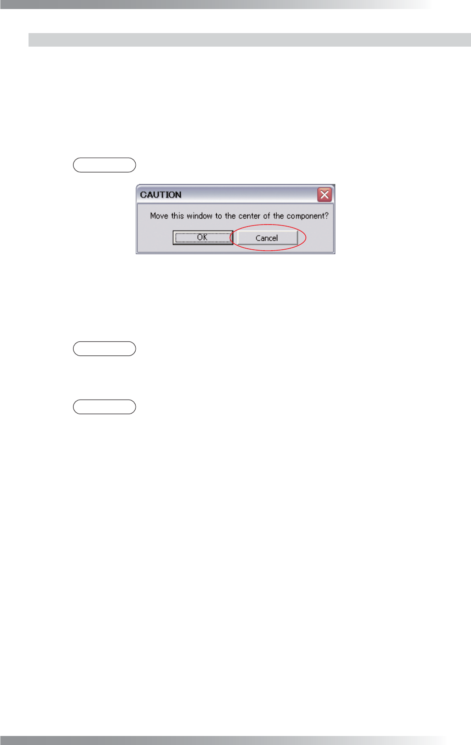
Step3: Press Add in the lower side of the dialog. The dialog shown in Figure 1-78 appears and
press Cancel. The image surrounded by inspection window appears.
NOTE
Press Delete and Inspect, then the reference image is deleted.
Figure 1-78 Dialog of ImageMatchEx
Step4: Adjust the value of SearchRangeX and SearchRangeY to defi ne the search range.
Step5: Enter values in the Upper and Lower fi eld.
NOTE
Standard values are 80 (Upper) and 0 (Lower).
Step6: Enter 99999 in the X fi eld and Y fi eld in the lower right side of the dialog.
NOTE
To use ImageMatchEx for position alignment, enter the tolerance of misalignment
value to X fi eld and Y fi eld.
Step7: Enter the appropriate vector into the Shift fi eld. Any value from V1 to V8 is available.
Select the vector according to the Memorize to fi eld of the Adjust window.
Step8: Enter V4 in Memorize to to refl ect this amount of misalignment to other algorithms.
Step9: Press Inspect. Make sure that the inspection is completed properly.