Programming_mail.pdf - 第77页
III- 3 Programming Manual Part III Inspection Algorithm 1.1.3 Setting Procedur e Step1: Select a lighting that displays electrodes visually clear from the Lighting drop-down list. CAUTION Select three different kinds of …
III-2
Programming Manual
Part III Inspection Algorithm
1 Inspection Algorithm
1.1 New_ASC
1.1.1 Inspection Overview
New_ASC is the algorithm to correct misalignments between CAD data and actual component
positions. Inspection data is made based on CAD data but assembled components are easily shifted
from the position that CAD data assigns during a mounting process. Misalignments should be
corrected for proper inspections. The New_ASC algorithm automatically searches chip electrodes
based on its brightness level, and corrects misalignments (X axis, Y axis, θ).
New_ASC is also suitable to detect shifts. LTracking/WTracking are more suitable for chip components
whose electrodes are visually unclear or IC components.
Refer to Part III 1.2 LTracking / WTracking.
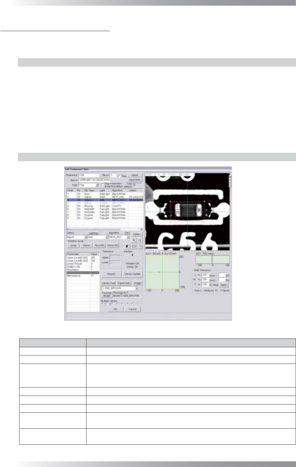
1.1.2 Parameter Setting
Figure 1-1 New_ASC
Parameter Description
Lighting Select a lighting that displays electrodes visually clear.
Algorithm Select New_ASC.
Upper Level[0-255],
Lower Level[0-255]
Upper Level is the upper limit of the brightness level. Lower Level is the lower
limit of the brightness level. Enter 255 in the Upper Level fi eld. Enter an
appropriate value to display an electrode clearly in the Lower Level fi eld.
Level2 Result Enter 0.
Shift[V1-V8] Enter 0.
Resolution Enter 1.
Memorize to
Enter V1 to register the amount of misalignment.
Enter V1 in the Shift fi eld to refl ect amount of a misalignment to other algorithms.
The graph in the lower
right side of the dialog
Displays the Shift amount by coordinates (X, Y) and angle (θ) in graphs.
Table 1-1 Parameter of New_ASC
III-3
Programming Manual
Part III Inspection Algorithm
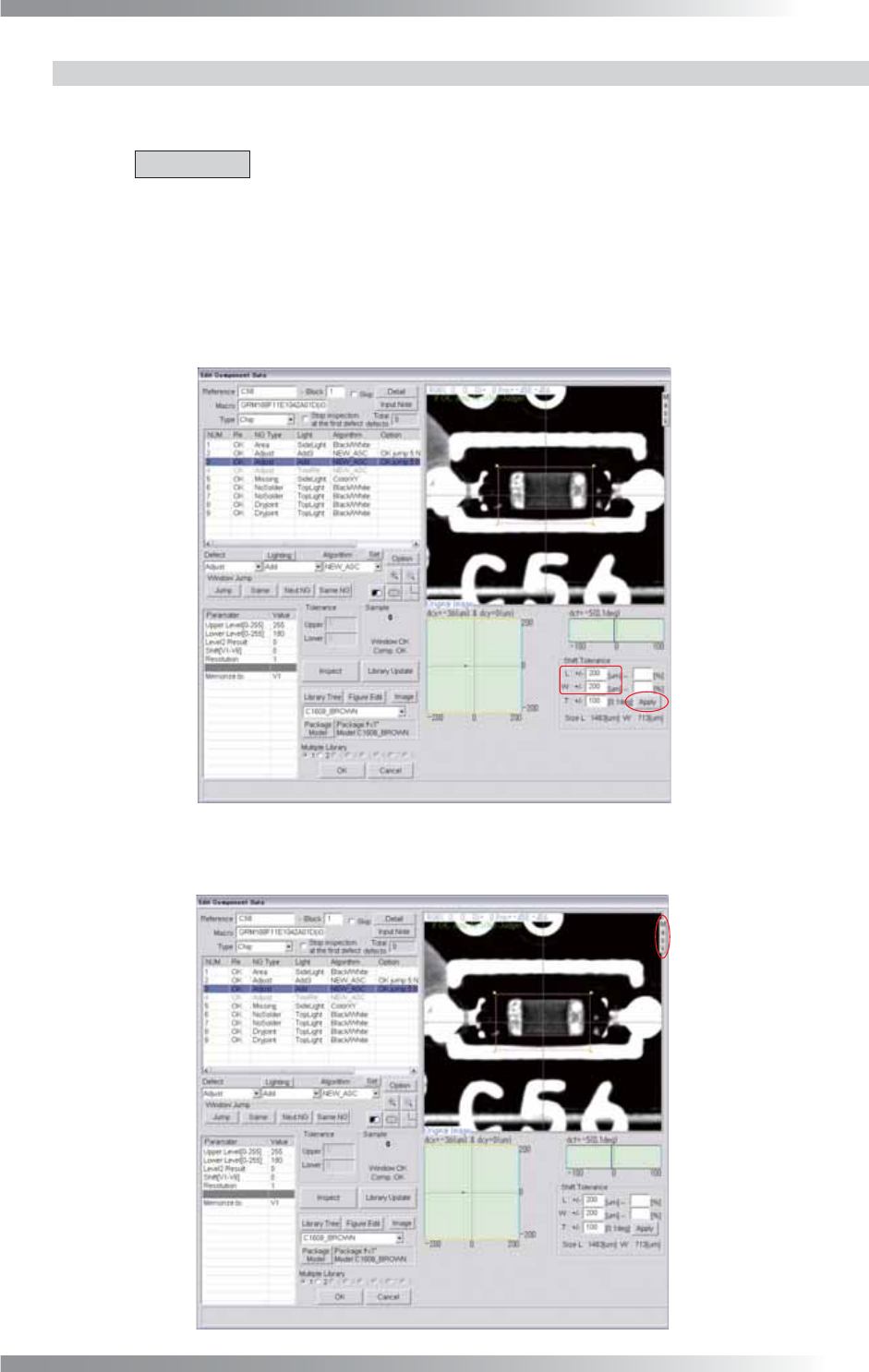
1.1.3 Setting Procedure
Step1: Select a lighting that displays electrodes visually clear from the Lighting drop-down list.
CAUTION
Select three different kinds of lightings for three Adjust windows.
Step2: Adjust the size of the Adjust window to surround the component body.
The ideal window size is about 1.2 times larger than the component size.
Step3: Adjust the L and W values in Shift Tolerance and press Apply.
Make sure that the specifi ed OK range is appropriate.
Figure 1-2 Shift Tolerance
Step4: Press Mask.
Figure 1-3 Mask Setting
III-4
Programming Manual
Part III Inspection Algorithm
Step5: The Mask window appears.
Adjust the window size to surround the entire component body (including electrodes).
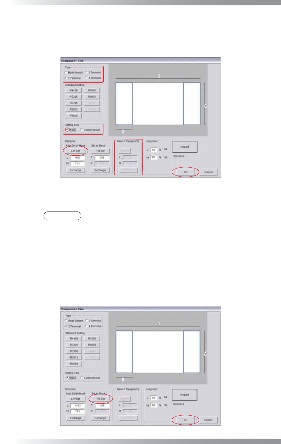
Step6: Press Set on the right side of Algorithm. The dialog shown in Figure 1-4 appears.
Figure 1-4 LW Setting
Step7: Select a component type from Type.
NOTE
If 4 Terminal is selected, the Search Range setting is required.
Step8: Check Mask in Setting Tool.
Step9: Press LW Set and OK.
Step10: The Mask window appears.
Adjust the window size to surround the electrodes on the one side.
Step11: Press Set on the right side of Algorithm. The dialog shown in Figure 1-5 appears.
Figure 1-5 TB Setting