Programming_mail.pdf - 第219页
V- 29 Programming Manual Part V Other Function 2.3 ECD Debug If any extra components are not detected or there are many false calls, adjust parameters. Step1: Right-click the red square frame and the dialog shown in Figu…
V-28
Programming Manual
Part V Other Function
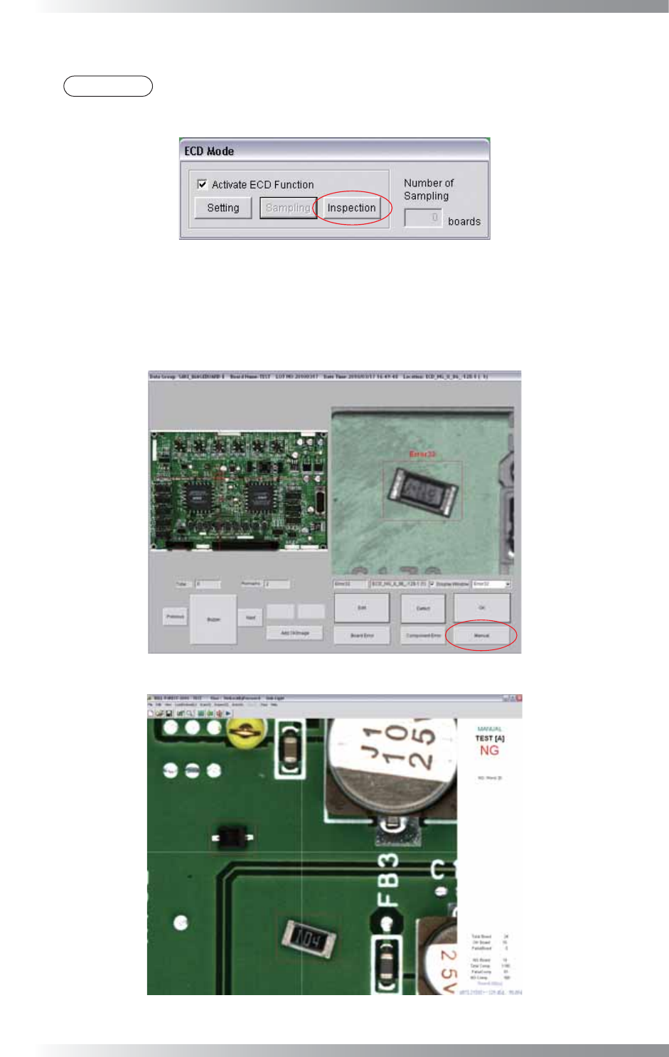
Step17: After 10 OK PCB sampled, ECD mode will be automatically switched from Sampling to Inspection.
NOTE
If Shift Inspection Mode Automatically of Parameter Setting shown in Figure 2-3 is
unchecked, press Inspection after completing sampling of OK PCBs.
Figure 2-22 Inspection Mode
Step18: Scan sample NG PCB and make sure that extra components are detected properly. If extra components
are detected, a red square frame is displayed in detection area. If any extra components are not detected
or these are many false calls, press Manual to stop auto inspection. Refer to Part V 2.3 ECD Debug.
Figure 2-23 Inspection of NG PCB
Figure 2-24 Detect Extra Component
V-29
Programming Manual
Part V Other Function
2.3 ECD Debug
If any extra components are not detected or there are many false calls, adjust parameters.
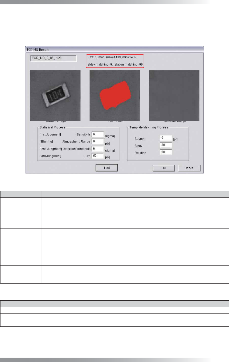
Step1: Right-click the red square frame and the dialog shown in Figure 2-25 appears.
Figure 2-25 ECD Debug
Item Description
num The number of NG area is displayed.
max
The number of pixels of the largest NG area is displayed.
If value of Size in Statistical Process is larger than value of max, judged as noise. The noise
is not inspected.
min
The number of pixels that shows area of smallest NG area is displayed.
stdev matching
Surround a NG area by a circumscribed quadrangle and calculate the following formula:
stdev matching =
(Circumscribed quadrangle area − NG area) / Circumscribed quadrangle area
If a Stdev value in Template Matching Process is bigger than a stdev matching value, the
NG area is not detected as an extra component.
relation matching
Calculates matching percentage of inspection PCB image and template image. If value of
Relation Matching in Template Matching Process is larger than value of relation matching
in the upper side of the dialog, the NG area is not detected as extra component.
Table 2-6 ECD Debug 1
Item Description
Current Image Detected extra component image is displayed.
NG Points
NG pixel is displayed in red.
Template Image
The latest sampled image is displayed as template image.
Table 2-7 ECD Debug 2
V-30
Programming Manual
Part V Other Function
Item Description
Sensitivity
Scans several OK PCBs. Calculates average values and standard deviation value.
If brightness level of inspection PCB differs from the average value greatly, the result will be NG.
Specify OK range of variability in Sensitivity.
Enter the bigger value to make the OK range wider.
Atmospheric Range
Brightness level of pixels that are judged NG in Sensitivity is averaged with brightness
level of surrounding pixels. Enter the bigger value to average pixels in wider area.
Detection Threshold
After Atmospheric Range, detect pixels which brightness level differs from the average
value. Enter the bigger value to make OK range wider.
Size
The size of the NG area which is detected in Detection Threshold is inspected in Size. If the
NG area is smaller than the specifi ed size, the NG area is eliminated from inspection target.
Search
The search area for matching inspection. Enter the bigger value to enlarge the search range.
Stdev
Surround the NG area by a circumscribed quadrangle to calculate following formula:
Stdev =
(Circumscribed quadrangle area) − (NG area) / (Circumscribed quadrangle area)
If it is smaller than the entered value (%), the result will be NG.
Relation
Calculates matching percentage of inspection PCB image and template image.
If relation matching in the upper side of the dialog is smaller than specifi ed value, the
result will be NG.
Table 2-8 ECD Debug 3
Step2: Refer to Table 2-9 and adjust values of Sensitivity, Atmospheric Range, Detection Threshold,
and Size. Press Test to update parameters. After all the adjustments are completed, press OK.
NOTE
If any extra components are not detected or there are many false calls, adjust values of
Stdev Matching or Relation Matching.
Item If extra component is not detected If there are many false calls
Detection Threshold Down Up
Atmospheric Range Down Up
Detection Threshold Down Up
Size Down Up
Stdev
Up Down
Relation
Up Down
Table 2-9 Measure of Parameter Adjustment
Step3: Press Inspect button on the tool-bar or select Inspect from the menu-bar and make sure that
extra components on the NG PCB can be detected. If extra components are not detected, adjust
parameters again.