Programming_mail.pdf - 第221页
V- 31 Programming Manual Part V Other Function Step4: Scan a target PCB. Sensitivity Brightness difference Pixels judged as NG in Sensitivity Atmospheric Range Averaging with brightness level of surrounding pixels Detect…
V-30
Programming Manual
Part V Other Function
Item Description
Sensitivity
Scans several OK PCBs. Calculates average values and standard deviation value.
If brightness level of inspection PCB differs from the average value greatly, the result will be NG.
Specify OK range of variability in Sensitivity.
Enter the bigger value to make the OK range wider.
Atmospheric Range
Brightness level of pixels that are judged NG in Sensitivity is averaged with brightness
level of surrounding pixels. Enter the bigger value to average pixels in wider area.
Detection Threshold
After Atmospheric Range, detect pixels which brightness level differs from the average
value. Enter the bigger value to make OK range wider.
Size
The size of the NG area which is detected in Detection Threshold is inspected in Size. If the
NG area is smaller than the specifi ed size, the NG area is eliminated from inspection target.
Search
The search area for matching inspection. Enter the bigger value to enlarge the search range.
Stdev
Surround the NG area by a circumscribed quadrangle to calculate following formula:
Stdev =
(Circumscribed quadrangle area) − (NG area) / (Circumscribed quadrangle area)
If it is smaller than the entered value (%), the result will be NG.
Relation
Calculates matching percentage of inspection PCB image and template image.
If relation matching in the upper side of the dialog is smaller than specifi ed value, the
result will be NG.
Table 2-8 ECD Debug 3
Step2: Refer to Table 2-9 and adjust values of Sensitivity, Atmospheric Range, Detection Threshold,
and Size. Press Test to update parameters. After all the adjustments are completed, press OK.
NOTE
If any extra components are not detected or there are many false calls, adjust values of
Stdev Matching or Relation Matching.
Item If extra component is not detected If there are many false calls
Detection Threshold Down Up
Atmospheric Range Down Up
Detection Threshold Down Up
Size Down Up
Stdev
Up Down
Relation
Up Down
Table 2-9 Measure of Parameter Adjustment
Step3: Press Inspect button on the tool-bar or select Inspect from the menu-bar and make sure that
extra components on the NG PCB can be detected. If extra components are not detected, adjust
parameters again.
V-31
Programming Manual
Part V Other Function
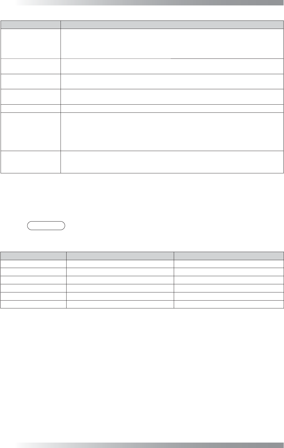
Step4: Scan a target PCB.
Sensitivity
Brightness difference
Pixels judged as NG in Sensitivity
Atmospheric Range
Averaging with brightness level of surrounding pixels
Detection Threshold
Pixels judged as NG in Detection Threshold
Size
Pixels of NG area
from surrounding
Brightness difference
from surrounding
Brightness difference
from surrounding
Brightness difference
from surrounding
Figure 2-26 Detection of Extra Component
V-32
Programming Manual
Part V Other Function
2.4 ECD Mask Function
ECD mask function can specify an area that is excluded from ECD inspection. The setting can be used to
reduce false calls such as no-polarity chips as well as unique barcode given to each PCB.
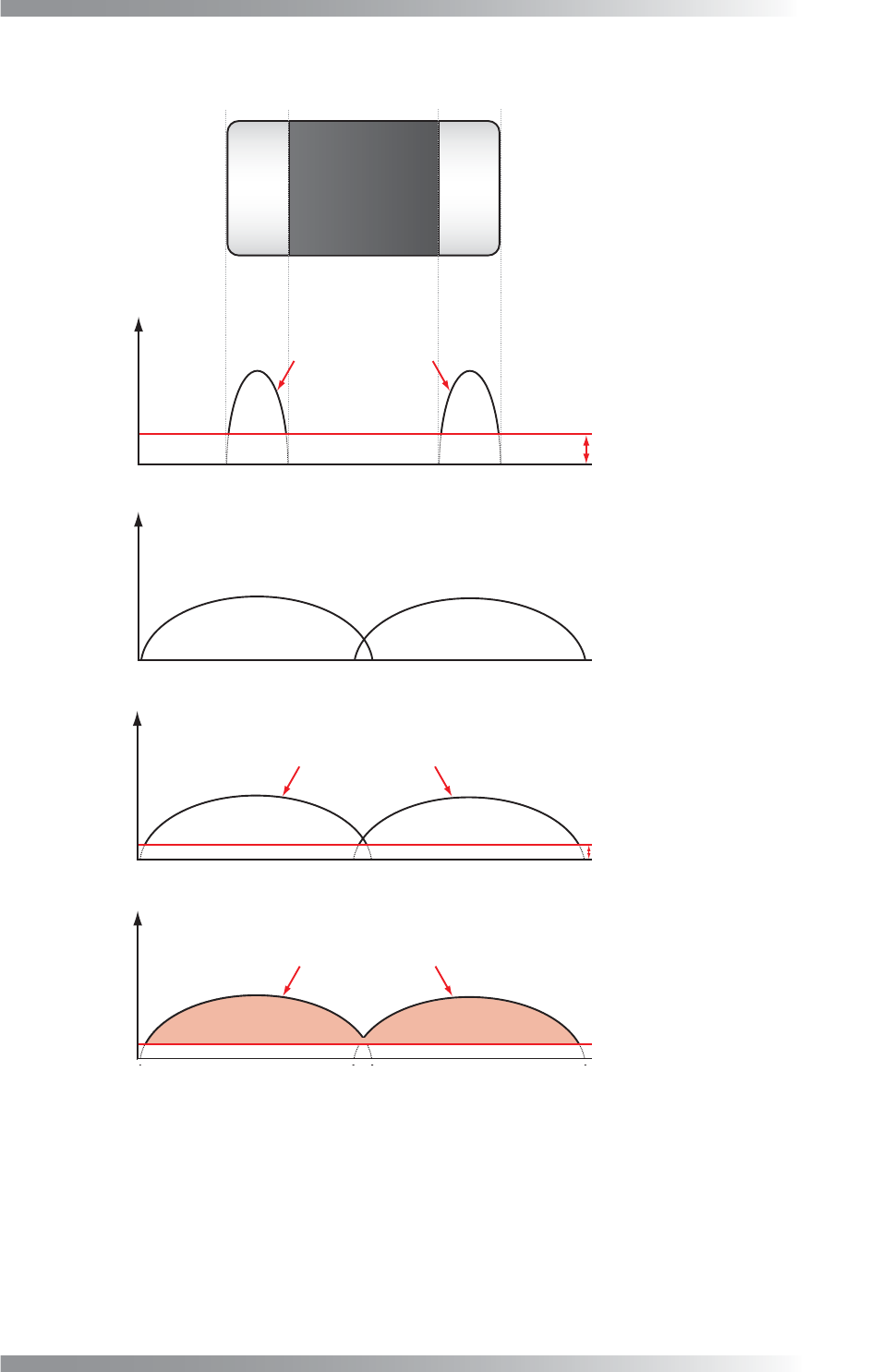
Step1: Right-click the component to mask and the dialog shown in Figure 2-27 appears.
Figure 2-27 Edit Component Data Dialog
Step2: Selected inspection window size is range to apply mask. Select inspection window and press
Option.
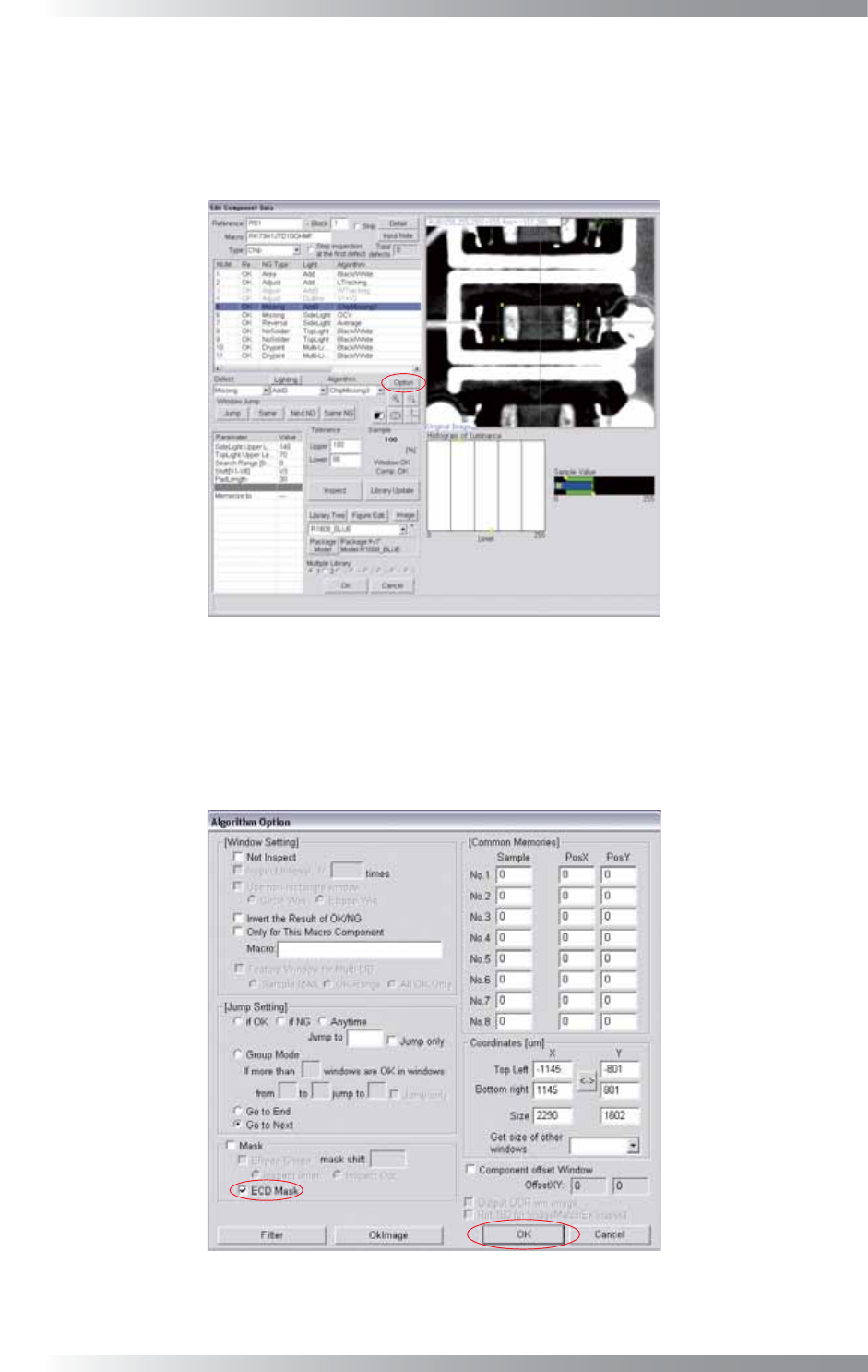
Step3: Check ECD Mask and press OK.
Figure 2-28 ECD Mask
Step4: Proceed to Step10 in Part V 2.2 Inspection procedure.