Programming_mail.pdf - 第27页
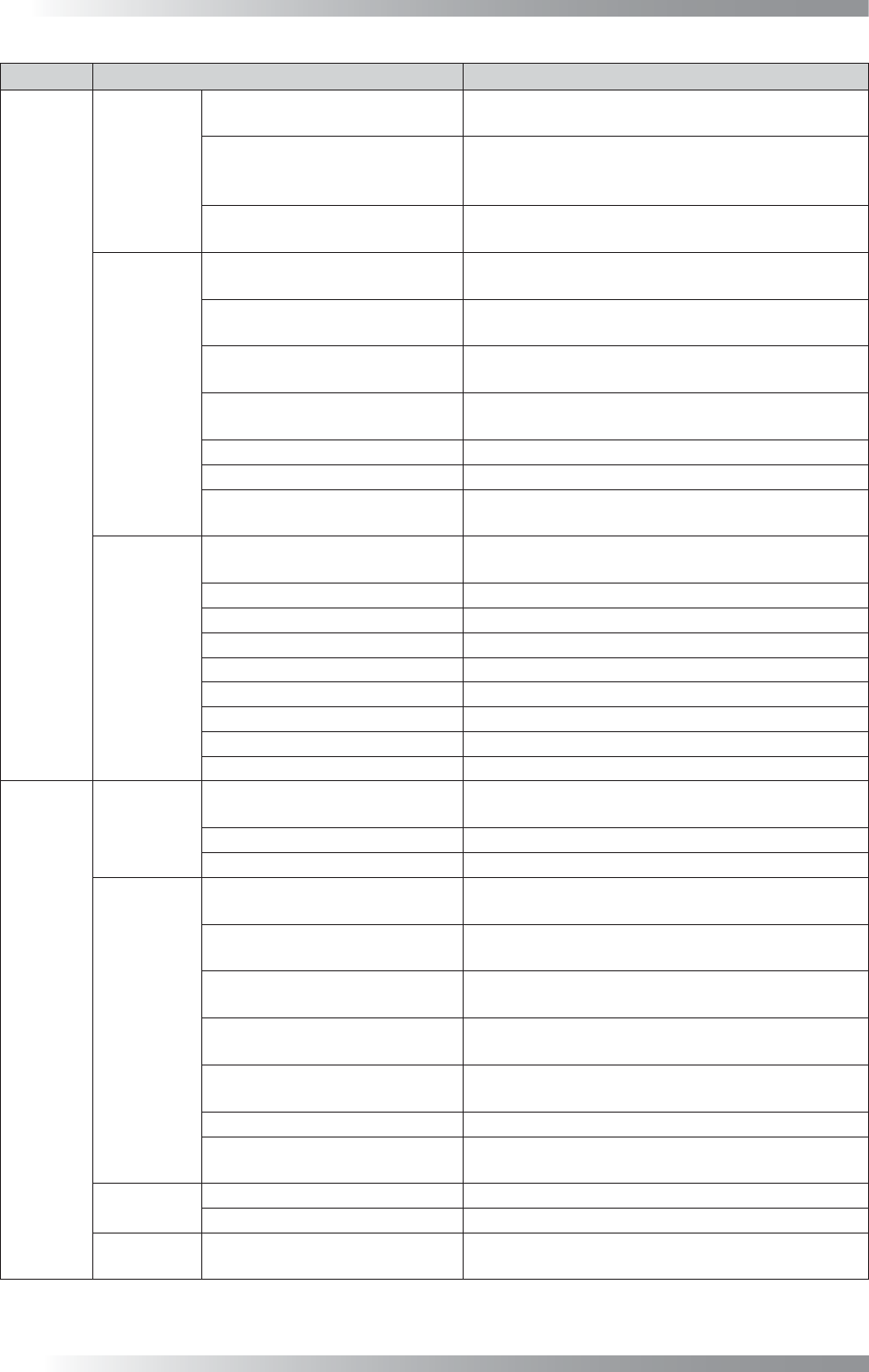
I- 19 Programming Manual Part I Basic Operation T ab Item Description Signal OK/NG Output for next machine ON at NG T urns the signal (OK/NG Out) on if NG is detected. T urns it off if OK is detected. ON at OK T urns the…
I-18
Programming Manual
Part I Basic Operation
Tab Item Description
Auto
Warning
Operator Call at Mark Error
Conducts an operator call if a mark error occurs in
the auto mode.
Use Air Pressure Sensor
Conducts an operator call if air pressure of the
machine falls lower than the specifi ed level in the
auto mode.
Operator Call at Defects are
Detected
Conducts an operator call if NG is detected in the
auto mode.
Monitor Mode,
Debug Mode
Check Board After Exchanging
in Monitor Mode
The confi rmation dialog is displayed after PCB is
unloaded.
Check Board Inside in Monitor
Mode
At NG detection, the confi rmation dialog appears
with the PCB inside the machine.
Monitor Mode:
Buzzer Button Disable
Invalidates the function to stop an alarm if an NG
is detected.
Enable judgement button after
click component image
Enables OK after clicking the image if a false call
occurs (inline machine only).
Disable ALL OK button ALL OK is disabled.
Monitor Mode Automatically runs in the monitor mode.
Correcting OCR in Monitor Mode
Displays the registered characters of OCR and
current result.
Others
Screen Saver
The screen saver is activated after fi ve minutes
standby state.
Check Next Board
Check whether two PCBs are loaded.
Unload when Mark Error
Unloads the PCB if mark error occurs.
Save Detected Images Saves NG images in inspection data folder.
Auto Load Model Not available.
Continuous Drive in Pass Mode
Turns a motor consistently during the Pass mode.
Must input Model Name
Enter model name.
WinXP Super Thread
Unloads the PCB after scanning (Windows XP only).
Using Accelerating Method Accelerates processing speed of algorithm.
Display
Display
Set Scale 1:1 in Debug Mode
Displays debug mode images at the same
magnifi cation.
New Editor (Beginner mode)
Simplifi es Edit Mode.
Legacy display (Non BF+) Not available.
Programming
Display History Diagram
Displays sample graphs of Black/White in the
histogram.
Make Dry-joint Window
Automatically adds an inspection window for a
dryjoint if an IC inspection data extracted.
Set Binary Image on Upper/
Lower Level
Not available.
Display Statistic History
Diagram
Records the history of sample values of Black/
White and display in the histogram.
Link Library Automatically
Updates a library to the latest version
automatically when selecting inspection data.
Apply Library to the Bottom Side
Not available.
Use Multiple-Library
If multiple libraries need to be used, check Use
Multiple-Library.
System
Shutdown Windows Shutdowns Windows at BF1 termination.
Check Servo Not available.
Inspection
Data Selection
Don’t Show Folder Property
The folder property is not displayed when an
inspection data is selected.
I-19
Programming Manual
Part I Basic Operation
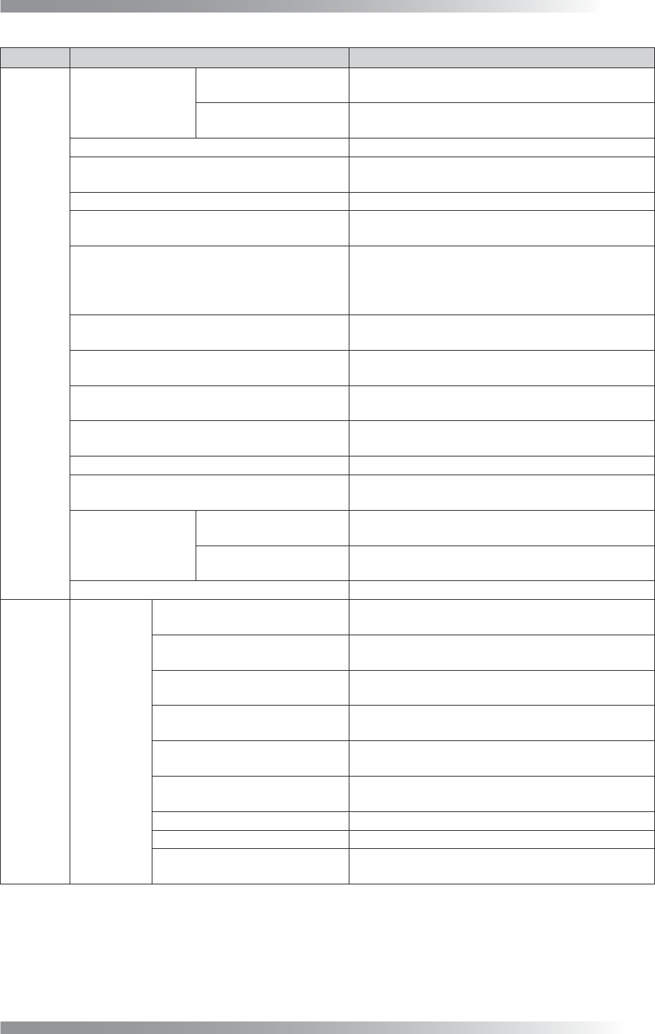
Tab Item Description
Signal
OK/NG
Output for
next machine
ON at NG
Turns the signal (OK/NG Out) on if NG is detected.
Turns it off if OK is detected.
ON at OK
Turns the signal (OK/NG Out) to off if NG is
detected. Turns it on if OK is detected.
Reset OK/NG Signal after Unloading PCB
Resets OK/NG signals right after unloading PCB.
For SMEMA Standard
Used to connect to upstream/downstream
machines by SMEMA.
FUJI Mounter Not available.
Output Busy-Out Signal before
Ready-In Signal from next machine
Outputs the Busy Out signal before the Ready-in
signal is input from downstream machines.
Reset Ready Signal after Loading
(No Preconveyor, Not SMEMA)
In the default setting, the Ready Out signal is reset
when a PCB passes an entrance sensor.
When it is set, the Ready Out signal is reset after
the PCB is loaded. Not available with SMEMA.
Reset Ready-Out Signal,
when entrance sensor is touched (QA/QC)
Not available.
Send Ready Signal when there is no PCB
Outputs the Ready signal to upstream machines if
there is no PCB inside the machine.
Set Ready Signal during Unload if inspection is OK
Outputs the Ready signal when unloading a PCB if
an inspection result is OK.
Connect to NG Buffer with Board ID
If using NG buffer, check Connect to NG Buffer
with Board ID.
Send OK/NG, Surface A/B info by Comport
Outputs the OK/NG signal from Comport.
Set Ready Signal when sensor detected
Outputs the Ready signal while the PCB entrance
sensor is activated.
OK/NG Input from
previous machine
ON at NG
Turns the signal (OK/NG Out) on if NG is detected.
Turns it off if OK is detected.
ON at OK
Turns the signal (OK/NG Out) to off if NG is
detected. Turns it on if OK is detected.
OK/NG separated Signal Outputs the OK/NG signal separately.
Barcode
Barcode
Use Barcode Reader
If using a barcode-reader (either fi xed or handy
type), check Use Barcode Reader.
Reader is Set Out of BF
If using a fi xed type barcode-reader, check Reader
is Set Out of BF.
Use Handy Barcode for Hero
Machine
Not available.
Inspect Both Side by One
Barcode
Not available.
Two Dimension Barcode
If using a 2D barcode-reader, check Two
Dimension Barcode.
Not Input Text Reader
If using a barcode-reader used without text input (e.g.,
TOKEN models), check Not Input Text Reader.
Com2 (Com1 Unchecked) Not available.
Print Shift Data (SKP)
Not available.
Multi Head Reader
If using a barcode-reader of multi head, check
Multi Head Reader.
I-20
Programming Manual
Part I Basic Operation
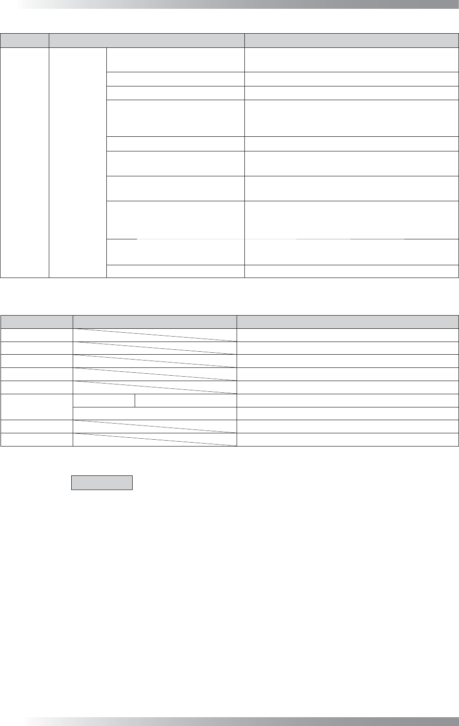
Tab Item Description
Barcode
Option
Select the Board by Barcode
If using barcodes to select data, check Select the
Board by Barcode.
Compare Barcode
Makes comparison with registered barcode information.
Input Barcode on BF-RP1
Enter barcode information on BF-RP1.
Don’t Change Jump Value
To prevent changing the jump setting automatically if an
inspection item is added to or deleted from the data by
the jump function, check Don’t Change Jump Value.
Read Barcode While Loading
Reads barcodes while loading a PCB.
Wait for Barcode Recognition
Retries until a barcode-reader succeeds to read a
barcode.
Don’t Popup Input Dialog while
Read Barcode Error
Outputs the current date name NG fi le if barcode
reading is failed.
Show Skip Message
Displays Some components are skipped to
inspect on the lower left of the screen, if there is a
component to be skipped in an inspection.
Barcode on Two Sides
If managing a number of double-side PCBs by one
barcode, check Barcode on Two Sides.
Change abnormal char to *
Table 2-1
System
Parameter List 1
Tab Item Description
Output File *
Machine *
Conveyor *
Calibration *
Origin *
Hardware1
Conveyor 2 Speed Conveyor
Use if validating a board delay sensor.
Other Items *
Hardware2 *
Camera *
Table 2-2
System
Parameter List 2
CAUTION
Regarding the items with *, these are for Saki engineer only.