Programming_mail.pdf - 第243页
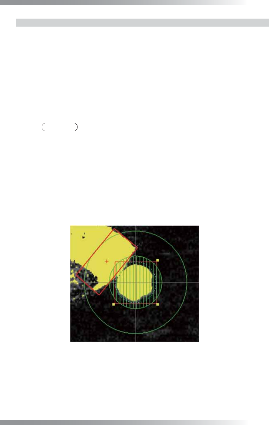
V- 53 Programming Manual Part V Inspection Data 4.8.2 Setting Procedur e of Bridge Inspection Step1: Press BRIDGE button. Step2: Check Inspect Bridge . Step3: Check Dedicated . Step4: Adjust the Coverage value so the adj…
V-52
Programming Manual
Part V Inspection Data
4.8 Bridge Inspection Setting
Bridge inspection detects the solder bridge between pads.
4.8.1 Parameter of Bridge Inspection
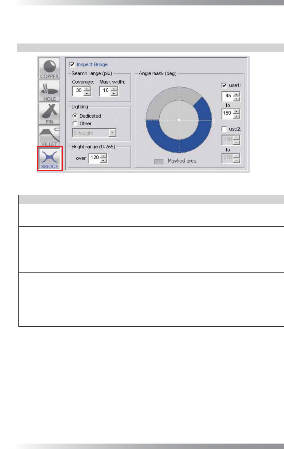
Figure 4-16 Bridge Inspection Setting
Parameter Description
Inspect Bridge
To activate bridge inspection, check Inspect Bridge.
To disable bridge inspection, Un-check Inspect Bridge.
Buttonʼs color is displayed as gray.
Coverage
The inspection area is specifi ed by width (pixel value) from the dotted line circle.
The inspection area is in the green circle except the area netted.
Enter the bigger value to enlarge the inspection area.
Mask width
Specifi es a “no inspection” area in an inspection area set in Coverage by a width (pixels)
from a dotted line circle.
Use this parameter if a pad edge is uneven. Set a mask so a solder fi llet is covered.
Lighting Select a lighting. Default setting is Dedicated.
Bright range
Shows the pixels of a specifi c brightness level which is set in Bright range in yellow.
In Bridge inspection, a yellow area will be searched in an inspection area, and if it
penetrates an inspection area, NG will be reported.
Angle mask
Specifi es a “no inspection” area in an inspection area set in Coverage by angle.
This parameter is used to exclude specifi c angles such as a PCB pattern or silk print
from an inspection area. Two Angle mask can be set.
Table 4-8 Parameter of Bridge Inspection
V-53
Programming Manual
Part V Inspection Data
4.8.2 Setting Procedure of Bridge Inspection
Step1: Press BRIDGE button.
Step2: Check Inspect Bridge.
Step3: Check Dedicated.
Step4: Adjust the Coverage value so the adjacent pin edge is included in the inspection area.
Specify the inspection area by the width (pixels) from the dotted line circle. The inspection
area is inside the green circle excluding the netted (masked) area. If the value gets bigger,
the search area becomes larger.
NOTE
If the solder and the clinch pin end are not displayed clearly by Dedicated, check
Other and select a lighting from the drop-down list.
Step5: If the edge of the pad is uneven, set the Mask width value. Specifi es the “no inspection”
area in the inspection area set in Coverage by the width (pixels) from the dotted line circle.
Set the mask so the solder is covered.
Step6: To exclude specifi c angles such as a PCB pattern or silk print from an inspection area, set
the Angle mask value. Specifi es the “no inspection” area in the inspection area set in
Coverage by angle. Two angle masks can be set.
Step7: Enter a value into the Bright range fi eld to detect solder.
Figure 4-17 Bridge Inspection
V-54
Programming Manual
Part V Inspection Data
5 Inspection Selection
Inspection selection is an effective function to manage inspection data of its product variations.
5.1 Inspection Overview
Some components are not mounted in different variations even in the same design. Componentʼs shapes
and colors may also differ from supplier to suppliers. In those cases, different variation of the inspection data
can be applied without making new inspection data with Inspection selection function. Inspection selection
achieves to reduce time for data creation and to manage inspection data easily.
5.2 Type of Inspection Selection
5.2.1 Skip Inspection
Skips arbitrarily selected components. The function is useful if components are missing as PCB
version differs.
5.2.2 Do Inspection for Not Placed
Only inspect missing component for arbitrarily selected components. If there is no component, the
result will be OK.
This is used when inspecting whether components which do not have to be mounted on certain
versions of PCB are mounted or not.
5.2.3 Exchange Macro
Apply arbitrarily macro for arbitrarily selected components.
Because libraries can be made for each macro, multiple libraries can be applied to the same
component.
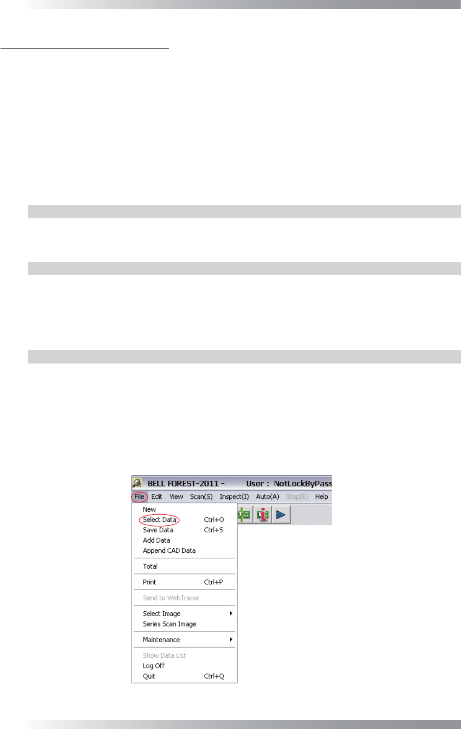
5.3 Setting Procedure
Step1: Select File > Select Data from the menu-bar to open the inspection data.
Figure 5-1 Select Data