Programming_mail.pdf - 第56页
II- 12 Programming Manual Part II Inspection Data Step19: The CAD data will be extracted automatically. NOTE Once user de fi ne format is registered, extracting CAD data is easy if the same format is used from the next ti…
II-11
Programming Manual
Part II Inspection Data
Step16: Press Next to enter PCB size and PCB thickness manually. Enter necessary conditions to extract
these data automatically. Make sure that necessary data is correctly extracted in Result of
extraction, and press Next.
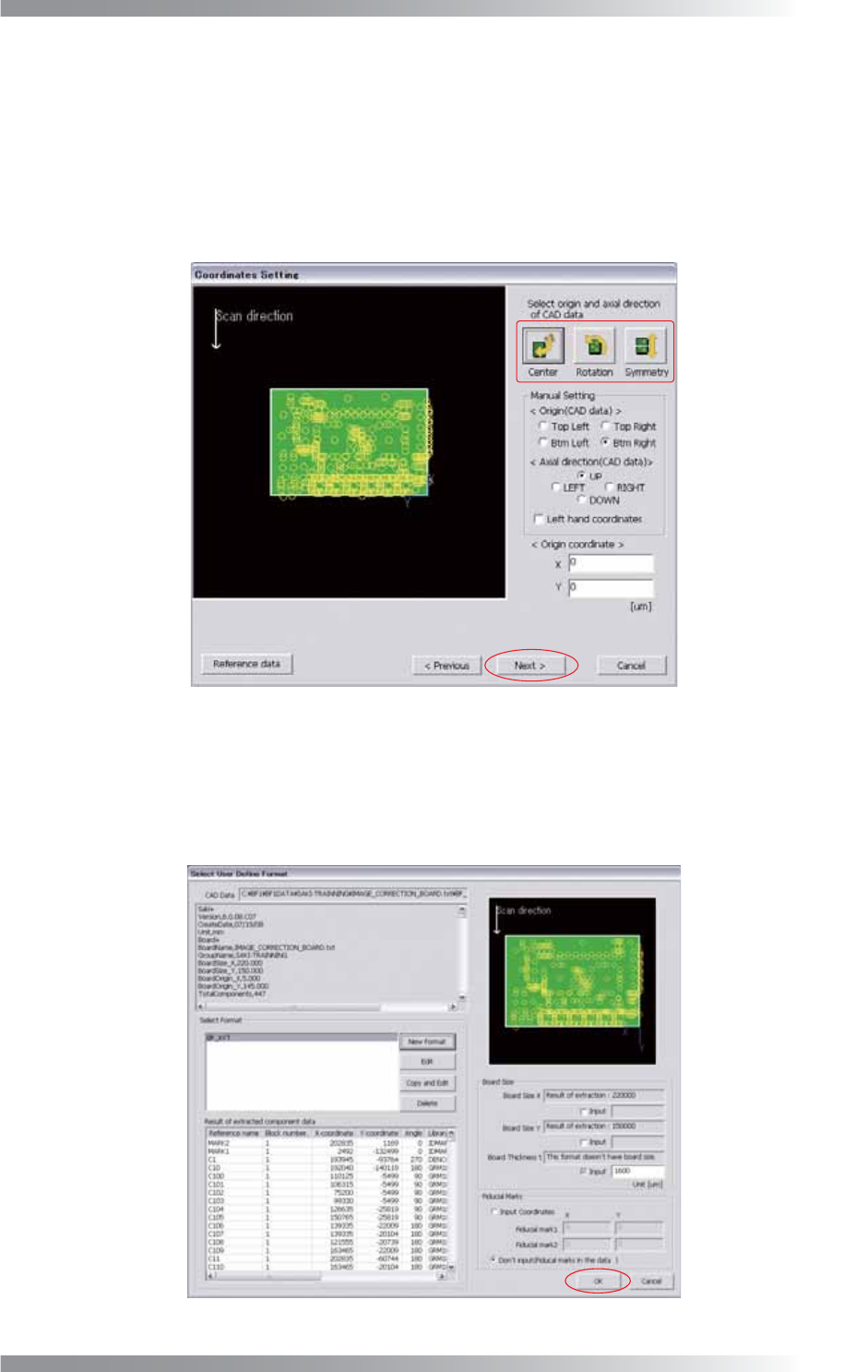
Step17: Press three buttons to match a CAD data origin with a machine origin. Starting from the left, Place
all data position inside of the PCB, Rotate all data 90° in counterclockwise direction, Flip all
data vertical. After all the settings are completed, press Next.
Figure 1-15 Coordinates Setting
Step18: Make sure that the component data is shown on the PCB image and Board Size is displayed.
If the data is not automatically extracted, enter the PCB size manually.
If the fi ducial mark data is not in the data, check Input coordinates and enter arbitrary
coordinates. After all the settings are completed, press OK.
Figure 1-16 User Defi ne Format
II-12
Programming Manual
Part II Inspection Data
Step19: The CAD data will be extracted automatically.
NOTE
Once user defi ne format is registered, extracting CAD data is easy if the same format is
used from the next time. Select the relevant format from Select Format. Set Board Size
and Fiducial Marks. Press OK.
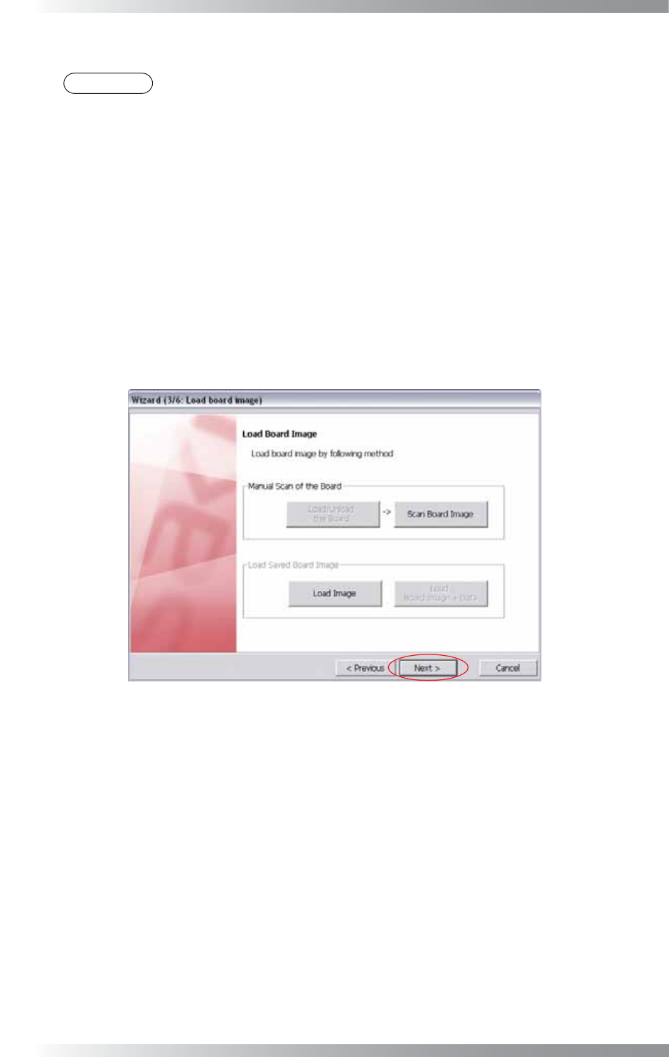
Step20: After CAD data is extracted, open the image. Press Load Image and specify the image fi le to open
the reserved image. The procedure to scan a PCB differs between benchtop machines and inline
machines.
In case of a benchtop machine
Set the PCB in the machine and press Scan Board Image.
In case of an inline machine
Adjust the conveyor rail width and set the PCB on conveyor rail. Press Load/Unload the Board.
Set the PCB in the machine and press Scan Board Image.
To unload the PCB, press Load / Unload the Board.
Figure 1-17 Wizard 3
Step21: Make sure that the PCB is scanned properly, and press Next.
II-13
Programming Manual
Part II Inspection Data
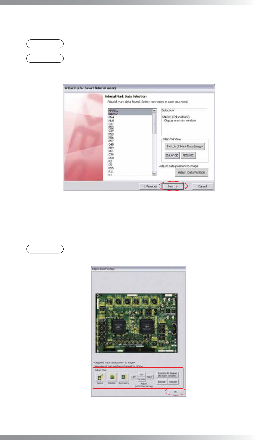
Step22: Select two fi ducial mark data from the list-box. The second selected fi ducial mark data is displayed.
Press Switch of Mark Data Image to display the other fi ducial mark data.
NOTE
Magnifi cation percentage of an image can be changed by pressing ENLARGE or REDUCE.
NOTE
As possible fi ducial mark data, the list-box shows 50 components data. These are top 50
of component data registered as fi ducial mark, component data including Mark, and
outlying component data from the center of a PCB.
Figure 1-18 Wizard 4
Step23: Press Adjust Data Position in Figure 1-18. The dialog shown in Figure 1-19 appears.
Press Adjust Tool to match the position of the component data with the image.
After all the adjustments are completed, press OK.
NOTE
The position of component data can be adjusted by dragging a mouse.
In addition, magnifi cation percentage can be changed by scrolling a wheel of a mouse.
Figure 1-19 Adjust Data Position
Step24: After all the settings are completed, press Next.