Programming_mail.pdf - 第111页
III- 37 Programming Manual Part III Inspection Algorithm 1.12.4 LiftedLead Setting Dialog Press Set in the right side of Algorithm . The dialog shown in Figure 1-40 appears. The parameter can be set in this dialog. Press…

III-36
Programming Manual
Part III Inspection Algorithm
1.12.3 Setting Procedure
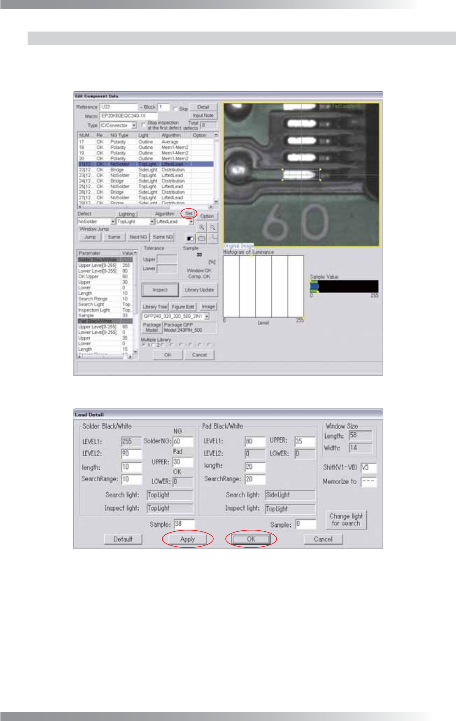
Step1: Select TopLight from the Lighting drop-down list.
Step2: Set the search range for the solder joint area. After changing the Search Range value in
Solder Black/White, press Inspect. Make sure that the pink dotted window is located on
the solder joint area.
Step3: Set the inspection area of the solder in the lead end. After changing the Length value in
Solder Black/White, press Inspect. Adjust the size of the pink dotted window.
Step4: Make sure that the OK Sample value in Solder Black/White is in the between Upper and
Lower. If OK Sample value is out of Upper and Lower, increase the value of Lower Level
in Solder Black/White.
NOTE
The percentage of the specifi ed brightness level as NG is displayed.
Step5: Set the search area for the pad end area. After changing the Search Range value in Pad
Black/White, press Inspect. Make sure that the green dotted window is located on the pad
end area.
Step6: Set the inspection area of the solder in the pad end. After changing the Length value in Pad
Black/White, press Inspect. Adjust the size of the green dotted window.
Step7: Make sure that the OK Sample value in Pad Black/White is in the between Upper and
Lower. If OK Sample value is out of the Upper and Lower range, increase the value of
Upper Level in Pad Black/White.
Step8: Enter the appropriate vector into the Shift fi eld. Any value from V1 to V8 is available.
Select the vector according to the Memorize to fi eld of the Adjust window.
Step9: Right-click the LliftedLead inspection item list and select Parameter Copy to copy the
parameter to other leads.
Step10: Press Jump and adjust the inspection window size of the lead on each corner.
Step11: Press Inspect. Make sure that the inspection is completed properly.
III-37
Programming Manual
Part III Inspection Algorithm
1.12.4 LiftedLead Setting Dialog
Press Set in the right side of Algorithm. The dialog shown in Figure 1-40 appears.
The parameter can be set in this dialog. Press Apply to apply the parameter.
After all the settings are completed, press OK.
Figure 1-39 LiftedLead Setting
Figure 1-40 Detail Settings of LiftedLead
III-38
Programming Manual
Part III Inspection Algorithm
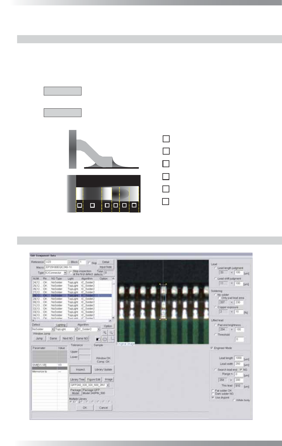
1.13 IC_Solder2
1.13.1 Inspection Overview
IC_Solder2 is the algorithm to inspect lead’s length and shift, solder condition and lifted lead in one
inspection window with high accuracy.
It automatically locates “inspection points” (lead end, lead base, pad end) on an IC component.
Inspection fl ow is as following; lead length, lead shift, solder, copper, and lifted lead.
CAUTION
If lead length or lead shift inspection is NG, all the following inspections, solder,
copper and lifted lead inspections are skipped.
CAUTION
IC_Solder2 is not available for two lighting system machine. It is also not valid in
combination with Part III 1.22 AS_Av_LeadLength.
㪈
㪉
㪊
㪋
㪌
㪍
㪈
㪉
㪊
㪋
㪌
㪍
Lead Base Area
Gull Wing Area
Lead End Area
Pad Lead Area
Pad Center Area
Pad End Area
Figure 1-41 Inspection of IC_Solder2
1.13.2 Parameter Setting
Figure 1-42 IC_Solder2