Programming_mail.pdf - 第126页
III- 52 Programming Manual Part III Inspection Algorithm Step7: This is the parameter setting for lead bend inspection. Select Gullwing from the Inspection parameter drop-down list. It calculates the average brightness v…
III-51
Programming Manual
Part III Inspection Algorithm
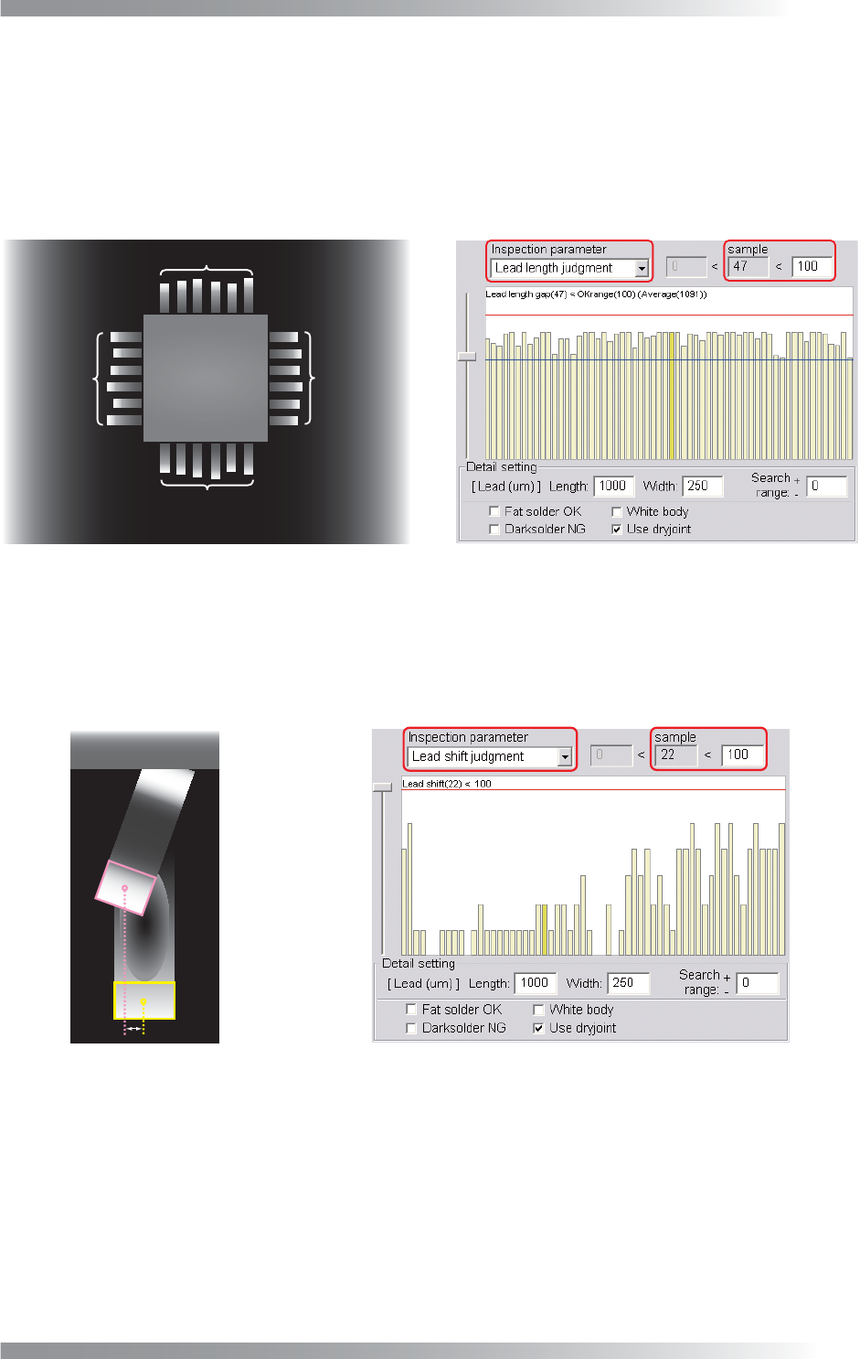
Step5: This is the parameter setting for lead length inspection. Select Lead length judgement from
the Inspection parameter drop-down list. It calculates the average value of leads length in
the same side of the component. The difference in amount between average length and
actual lead length is shown as the sample value. If the sample value is lower than OK range,
the result will be OK. The inspection logic is same as Part III 1.22 AS_Av_LeadLength.
Default is 100 [μm]. If necessary, change the value according to inspection accuracy.
Average value for leads length
Average
Average
Average
Average
in the same side of the body
- Selected lead length
Figure 1-62 Lead Length Judgement
Step6: This is the parameter setting for lead shift inspection. Select Lead shift judgement from the
Inspection parameter drop-down list. The shift amount from lead end area and pad end
area is shown as sample value. If the sample value is lower than OK range, the result will be
OK. Default is 100 [μm]. If necessary, change the value depends on inspection accuracy.
Lead End Area
Pad End Area
Figure 1-63 Lead Shift Judgement
III-52
Programming Manual
Part III Inspection Algorithm
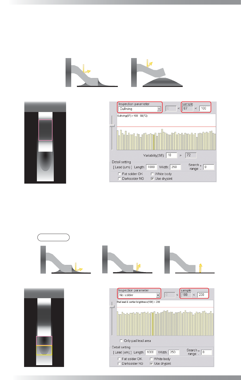
Step7: This is the parameter setting for lead bend inspection. Select Gullwing from the Inspection
parameter drop-down list. It calculates the average brightness value of gull wing area in the
same side of the component. The difference in amount between average brightness and actual
brightness is shown as the sample value. If the sample value is lower than OK range, the result
will be OK. Default is 100. If necessary, change the value according to inspection accuracy.
(a) Normal
(b) LiftedLead
High Brightness Low Brightness
Gull Wing Area
Figure 1-64 Lead Bend Inspection
Step8: This is the parameter setting for solder inspection. Select No solder from the Inspection
parameter drop-down list. It calculates average brightness level in pad lead area and pad
center area as sample value. If the sample value is lower than OK range, the result will be
OK. Default is 230. If necessary, change the value depends on inspection accuracy.
NOTE
The average brightness level is lower in case of no solder or insuffi cient solder.
(a) Normal
(b) Insufficient Solder
Low Brightness High Brightness
(c) No Solder
High Brightness
Pad Center Area
Pad Lead Area
Figure 1-65 Solder Inspection
III-53
Programming Manual
Part III Inspection Algorithm
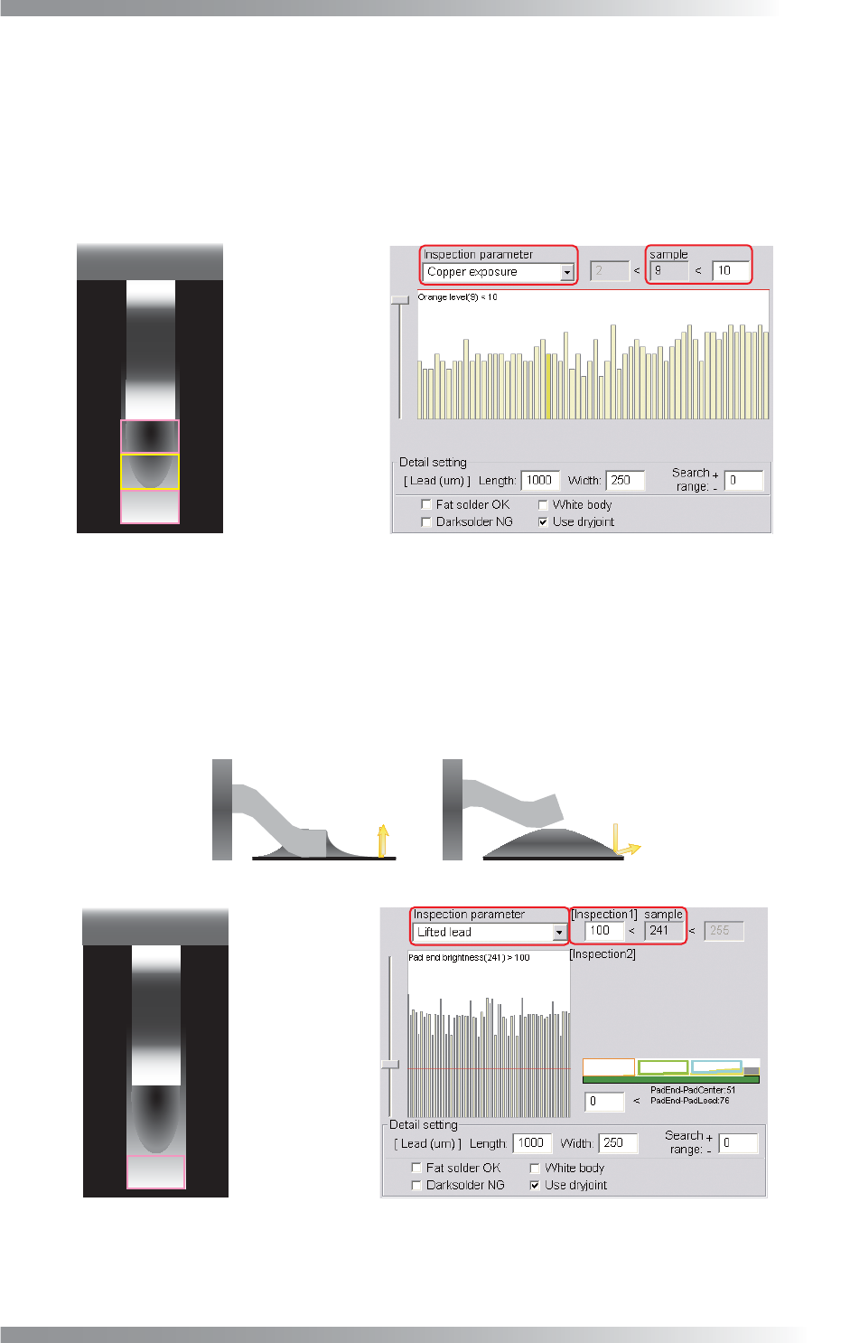
Step9: This is the parameter setting for copper exposure inspection. Select Copper exposure
from the Inspection parameter drop-down list. It is useful to detect copper area due to
insuffi cient solder. It calculate the percentage of copper color defi ned as more than 80% of
hue and color saturation and more than 60% of brightness in pad lead, pad center, and pad
end area. If the sample value is lower than OK range, the result will be OK. The default is
10%. If necessary, change the value depends on the solder condition.
Pad Center Area
Pad Lead Area
Pad End Area
Figure 1-66 Copper Inspection
Step10: This is the parameter setting for lifted lead inspection. Select Lifted lead from the Inspection
parameter drop-down list. Lifted lead inspection has two steps. First inspection calculates
average brightness level in pad end area. If the sample value is higher than OK range, the
result will be OK. Default is 100. If necessary, change the value according to the inspection
accuracy. If the fi rst inspection is NG, the second inspection shown in Step11 will be done.
(a) Normal
(b) LiftedLead
High Brightness
Low Brightness
Pad End Area
Figure 1-67 Lifted Lead Inspection 1