Programming_mail.pdf - 第89页
III- 15 Programming Manual Part III Inspection Algorithm 1.6.3 Setting Procedur e Step1: Select a lighting that the target component is visually clear from the Lighting drop-down list. Step2: Adjust the inspection window…
III-14
Programming Manual
Part III Inspection Algorithm
1.6 Length
1.6.1 Inspection Overview
Length is the algorithm to inspect component’s length.
Surround the component and around it by a window. Component’s length is calculated based on the
changes of brightness level in the window.
If the inspected component’s length is in OK range, the result will be OK.
Length is suitable for missing inspection of chip components.
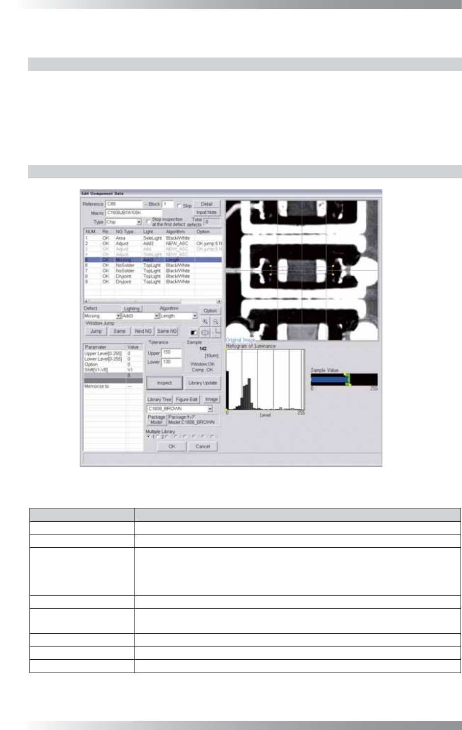
1.6.2 Parameter Setting
Figure 1-15 Length
Parameter Description
Lighting Select a lighting that the component is visually clear.
Algorithm Select Length.
Upper Level[0-255],
Lower Level[0-255]
Enter 0 in Upper Level and Lower Level if the component brightness level is
lower than the brightness level of a PCB.
Enter 255 in Upper Level and Lower Level if the component brightness level is
higher than the brightness level of a PCB.
Option Enter 0.
Shift[V1-V8]
Enter the appropriate vector. Any value from V1 to V8 is available.
Select the vector according to the Memorize to fi eld of the Adjust window.
Memorize to -
Memorize to Set the upper and lower limit of the OK range.
Sample
Shows the length of the component by 10 μm.
Table 1-6 Parameter of Length
III-15
Programming Manual
Part III Inspection Algorithm
1.6.3 Setting Procedure
Step1: Select a lighting that the target component is visually clear from the Lighting drop-down list.
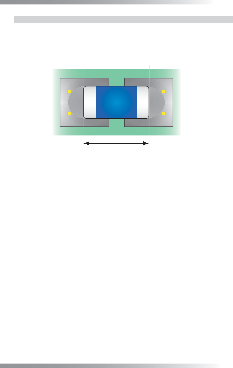
Step2: Adjust the inspection window to be longer than the length of the component in the longitudinal
direction. In lateral direction, adjust the inspection window to be shorter than the component.
Length
Figure 1-16 Inspection Window of Length
Step3: Verify the value of Upper Level and Lower Level. Enter 0 in Upper Level and Lower Level
fi eld if the component brightness level is lower than the PCB. Enter 255 in Upper Level and
Lower Level fi eld if the component brightness level is higher than the PCB.
Step4: Set the OK range by setting Upper and Lower. Sample shows the component length by
10 μm.
Step5: Enter the appropriate vector into the Shift fi eld by selecting from V1 to V8 according to the
vector used in the Memorize to fi eld in the Adjust window.
Step6: Press Inspect. Make sure that the inspection is completed properly.
III-16
Programming Manual
Part III Inspection Algorithm
1.7 Peak
1.7.1 Inspection Overview
Peak is the algorithm to inspect based on peak value within an inspection window.
If the peak of brightness level is in OK range, the result will be OK.
Brightness level within an inspection window can be obtained stably because this algorithm is not
affected by noise. Peak is suitable for a missing inspection of IC components.
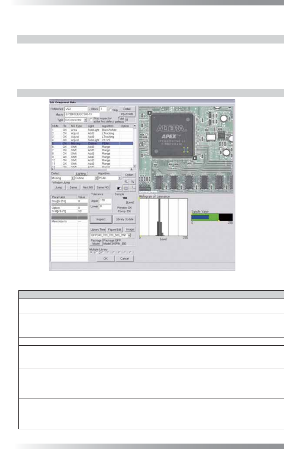
1.7.2 Parameter Setting
Figure 1-17 Peak
Parameter Description
Lighting
Select a lighting that displays the brightness level difference between the
component and the PCB visually clear.
Algorithm Select Peak.
Step[0-255]
Default is 8. The bar graph shows the number of pixels that is divided brightness
level by 8 in the graph in the lower right side of the dialog.
Option Enter 0.
Shift[V1-V8]
Enter the appropriate vector. Any value from V1 to V8 is available.
Select the vector according to the Memorize to fi eld of the Adjust window.
Memorize to -
Upper, Lower
Calculates a value intermediate between OK sample and NG sample value. If OK
sample value is smaller than NG sample value, enter intermediate value in Upper
fi eld and 0 in Lower fi eld. If NG sample value is smaller than OK sample value,
enter 255 in Upper fi eld and intermediate value in Lower fi eld.
Sample Shows the peak value within the inspection window.
The graph in the lower
right side of the dialog
The Histogram of Luminance bar graph shows the number of pixels of every
bright level. Sample value is the largest brightness which is distributed within
the inspection window.
Table 1-7 Parameter of Peak