Programming_mail.pdf - 第75页
Programming Manual Part III Inspection Algorithm III- 1 Inspection Algorithm
II-30
Programming Manual
Part II Inspection Data
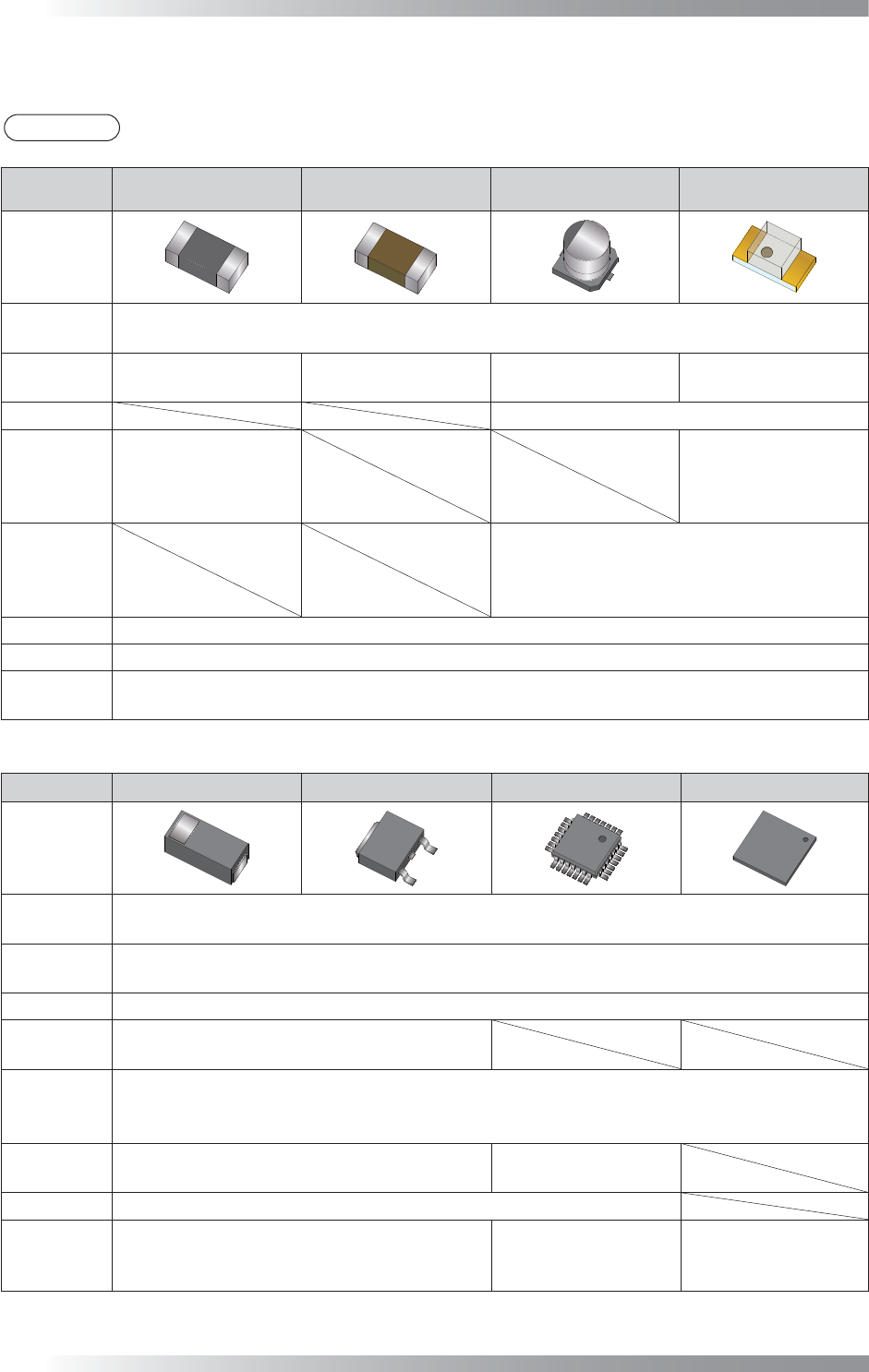
1.4 Major Algorithms Used for Inspections on Each Component
NOTE
According to component conditions, algorithms used may change.
NG type
Resistance Ceramic Capacitor
Aluminum
Electrolytic Capacitor
LED
Adjust
New_ASC
LTracking / WTracking
Missing
Average
Black/White
ColorXY
AreaColor
Average
Black/White
ColorXY
AreaColor
Polarity Diagonally
Reverse
Average
Black/White
Average
Black/White
ColorXY
AreaColor
Misalignment
Average
Black/White
ColorXY
AreaColor
No Solder
Black/White
Copper AreaColor
Lifted Lead
Lifted Chip
Black/White
AS_AV_LeadLength
Table 1-13 Major Algorithms Used for Inspections on Each Components1
NG type Diode Transistor SOP/QFP BGA
Adjust
New_ASC
LTracking / WTracking
Missing
Average
Black/White
Polarity Diagonally
Reverse
Average
Black/White
Misalignment
Average
Range
Black/White
No Solder
Black/White
Black/White
IC_Solder3
Copper AreaColor
Lifted Lead
Lifted Chip
Black/White
AS_AV_LeadLength
Black/White
AS_AV_LeadLength
IC_Solder3
Table 1-14 Major Algorithms Used for Inspections on Each Component 2

Programming Manual
Part III Inspection Algorithm
III-
1
Inspection Algorithm
III-2
Programming Manual
Part III Inspection Algorithm
1 Inspection Algorithm
1.1 New_ASC
1.1.1 Inspection Overview
New_ASC is the algorithm to correct misalignments between CAD data and actual component
positions. Inspection data is made based on CAD data but assembled components are easily shifted
from the position that CAD data assigns during a mounting process. Misalignments should be
corrected for proper inspections. The New_ASC algorithm automatically searches chip electrodes
based on its brightness level, and corrects misalignments (X axis, Y axis, θ).
New_ASC is also suitable to detect shifts. LTracking/WTracking are more suitable for chip components
whose electrodes are visually unclear or IC components.
Refer to Part III 1.2 LTracking / WTracking.
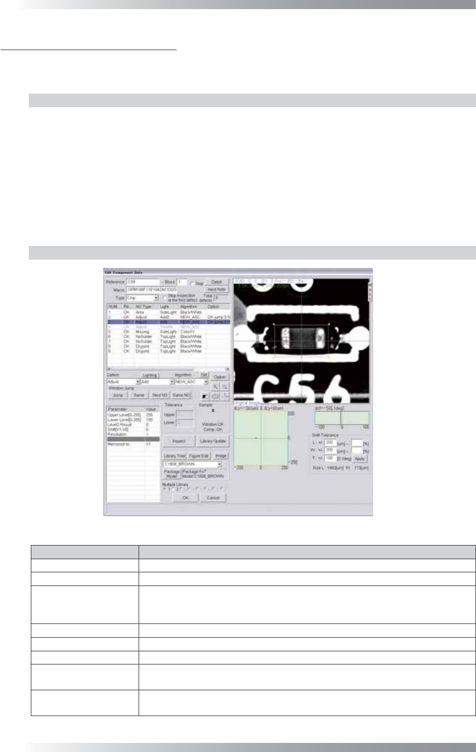
1.1.2 Parameter Setting
Figure 1-1 New_ASC
Parameter Description
Lighting Select a lighting that displays electrodes visually clear.
Algorithm Select New_ASC.
Upper Level[0-255],
Lower Level[0-255]
Upper Level is the upper limit of the brightness level. Lower Level is the lower
limit of the brightness level. Enter 255 in the Upper Level fi eld. Enter an
appropriate value to display an electrode clearly in the Lower Level fi eld.
Level2 Result Enter 0.
Shift[V1-V8] Enter 0.
Resolution Enter 1.
Memorize to
Enter V1 to register the amount of misalignment.
Enter V1 in the Shift fi eld to refl ect amount of a misalignment to other algorithms.
The graph in the lower
right side of the dialog
Displays the Shift amount by coordinates (X, Y) and angle (θ) in graphs.
Table 1-1 Parameter of New_ASC