Programming_mail.pdf - 第33页
I- 25 Programming Manual Part I Basic Operation XY Marking (Painting) Setup Check Marking in Figure 2-6 Search Data , select XYMARK and press Edit . The XY Painting Setup dialog shown in Figure 2-7 appears. Refer to T ab…
I-24
Programming Manual
Part I Basic Operation
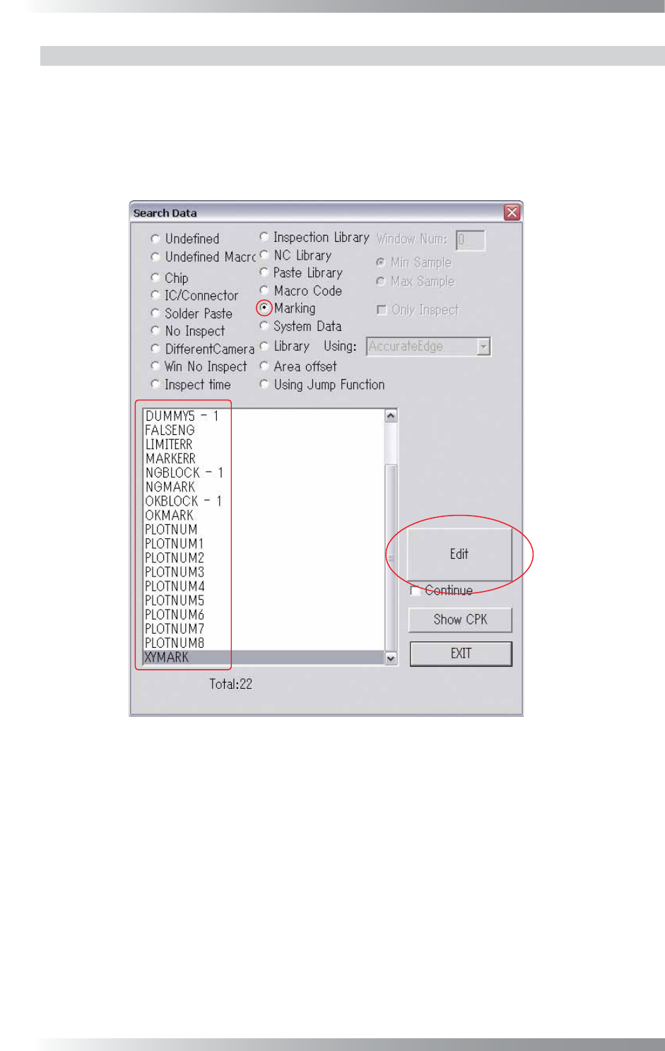
2.5.2 Setting by Type of Marking
Here describes the way to setup marking respectively.
Step1: Open the inspection data to change the marking setting.
Step2: Select Edit > Search from the menu-bar.
The Search Data dialog shown in Figure 2-6 appears.
Figure 2-6 Search Data
I-25
Programming Manual
Part I Basic Operation
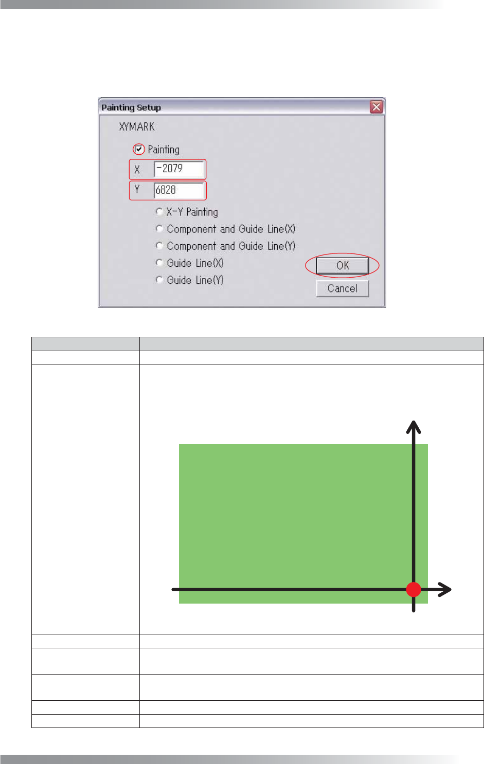
XY Marking (Painting) Setup
Check Marking in Figure 2-6 Search Data, select XYMARK and press Edit. The XY Painting Setup
dialog shown in Figure 2-7 appears. Refer to Table 2-4 XY Painting Setup and proceed the setup
procedures. After all the settings are completed, press OK.
Figure 2-7 XY Painting Setup
Item
Description
Painting
When checked, the XY painting (marking) function works.
XY Coordinates Setup
The marking positions for NG components can be specifi ed.
“X,Y = (325000, 5000) [μm]” is set as the marking origin (X,Y = (0, 0) [μm]) as
shown in Figure 2-8. If changing marking positions, enter coordinates from this
origin point.
Figure 2-8 XY Coordinates Setup
X-Y Painting
Puts marks on the specifi ed coordinates point.
Component and
Guide Line (X)
Puts two marks, one on the NG components, and the other on the axis of X
coordinates of the component.
Component and
Guide Line (Y)
Puts two marks, one on the NG components, and the other on the axis of Y
coordinates of the component.
Guide Line (X) Puts a mark on the axis of X coordinates of the NG component.
Guide Line (Y)
Puts a mark on the axis of Y coordinates of the NG component.
Table 2-4 XY Painting Setup
I-26
Programming Manual
Part I Basic Operation
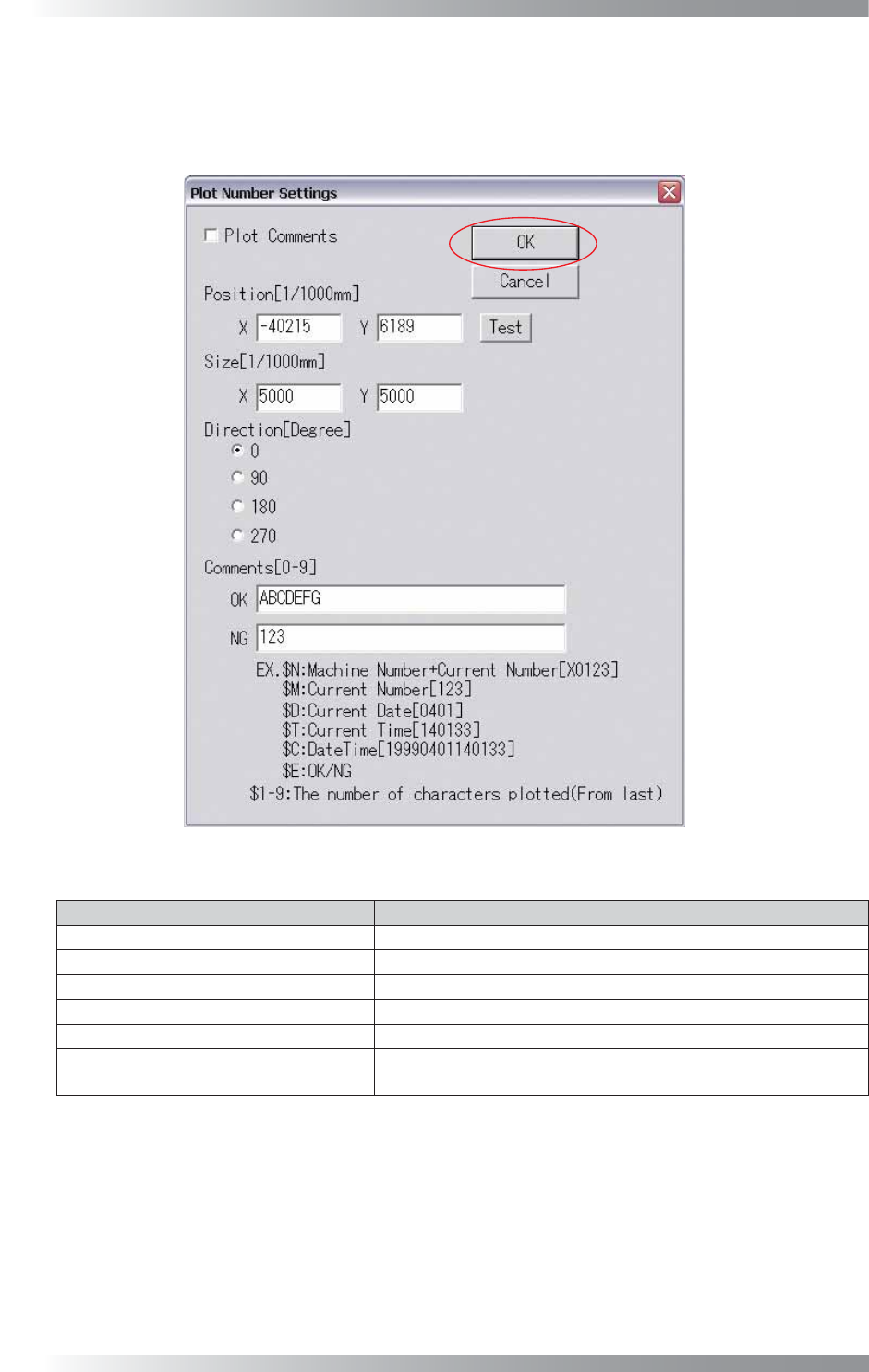
Plot Number Setup
Check Marking in Figure 2-6 Search Data, select PLOTNUM (Plot Number) and press Edit.
The Plot Number Settings dialog shown in Figure 2-9 appears. Refer to Table 2-5 Plot Number
Settings and proceed the setup procedures. After all the settings are completed, press OK.
Figure 2-9 Plot Number Settings
Item Description
Plot Comments
If plotting comments, check Plot Comments.
Position [1/1000mm]
Specifi es the central position to start plotting.
Size [1/1000mm] Specifi es the size of characters to plot.
Direction [Degree]
Specifi es the direction of characters.
Comments [0-9] Enter comments.
Test
Tests whether plotting can be performed correctly on the board
based on the specifi ed setup.
Table 2-5 Plot Number Settings