Programming_mail.pdf - 第148页
III- 74 Programming Manual Part III Inspection Algorithm 1.22 AS_Av_LeadLength 1.22.1 Inspection Ov er view AS_Av_LeadLength is the algorithm to inspect leads length of IC components by measuring length from lead base ar…
III-73
Programming Manual
Part III Inspection Algorithm
1.21.3 Setting Procedure
Step1: Set search range for the lead end area. After changing parameter of Search Range below
Lead Top Area, press Inspect. Make sure that the lead end area is surrounded by yellow
dotted line automatically or not.
Step2: Set inspection window size for lead end area. After changing parameter of Lead Top Area,
press Inspect. Adjust the size of the yellow dotted window.
Step3: Set search range for the lead base area. After changing parameter of Search Range below
LeadBase, press Inspect. Make sure that lead base area is surrounded by pink dotted line
automatically or not.
Step4: Set inspection window size for lead base area. After changing parameter of LeadBase,
press Inspect. Adjust the size of the pink dotted window.
Step5: Check Sample Value of OK lead. Enter the value (Sample Value plus 20) in Upper fi eld
and the value (Sample Value minus 20) in Lower fi eld.
NOTE
Sample value is distance of lead end area to lead base area.
Step6: Enter the appropriate vector into the Shift fi eld. Any value from V1 to V8 is available.
Select the vector according to the Memorize to fi eld of the Adjust window.
Step7: Right-click on ASLeadLength in the inspection item list and select Parameter Copy to
copy parameter to the other leads.
Step8: Press Jump and adjust inspection window size of the corner leads in each.
Step9: Press Inspect. Make sure that the inspection is completed properly.
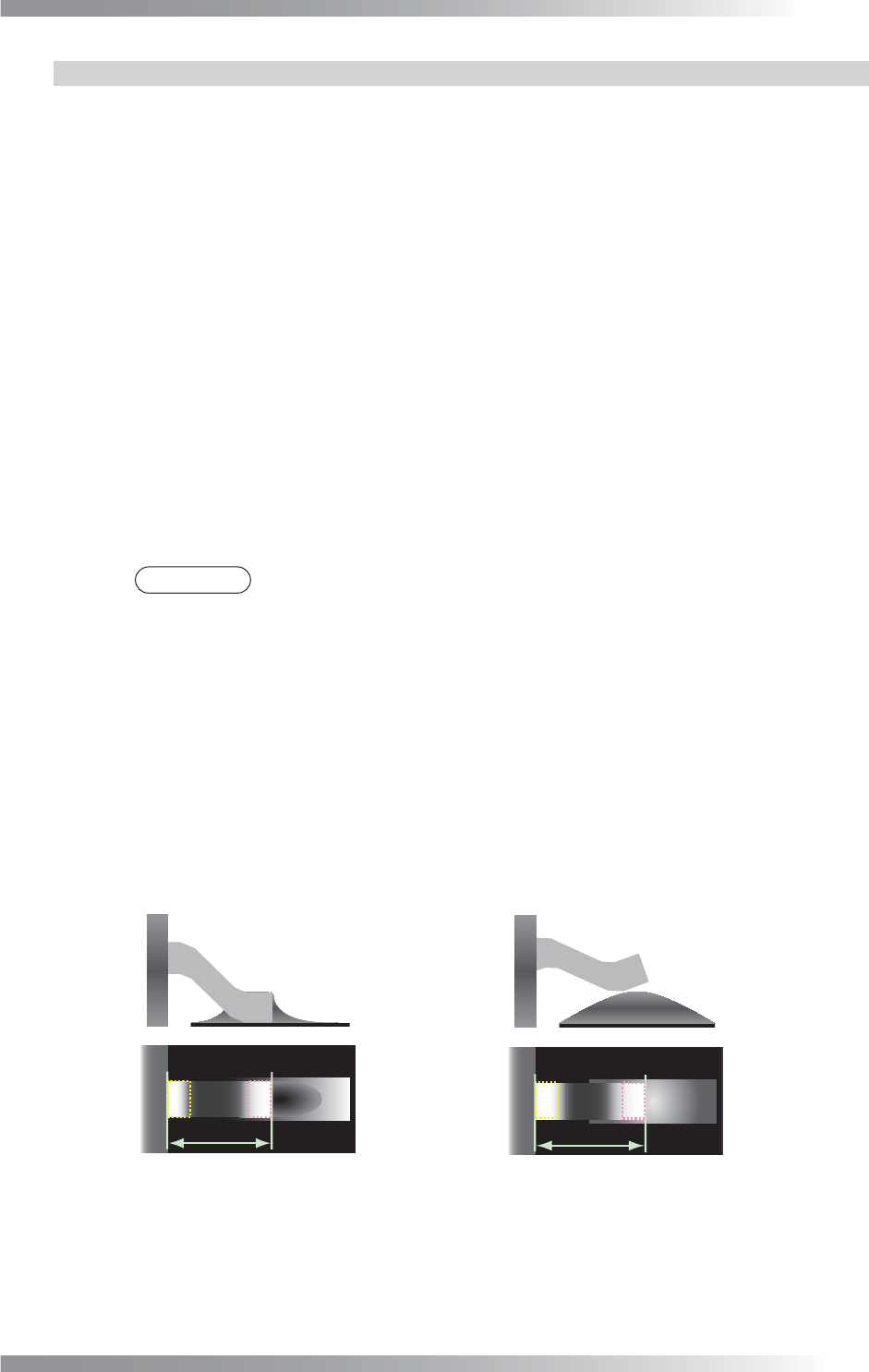
(a) Normal (b) Lifted Lead
The longer than (a)
Figure 1-89 LiftedLead Inspection by ASLeadLength
III-74
Programming Manual
Part III Inspection Algorithm
1.22 AS_Av_LeadLength
1.22.1 Inspection Overview
AS_Av_LeadLength is the algorithm to inspect leads length of IC components by measuring length
from lead base area to lead end area.
Scanning with TopLight, brightness level of Lead base area and lead end area are bright.
If lifted lead occurs, lead length is longer compare to normal condition.
Sample value of ASLeadLength is lead length but sample value of AS_Av_LeadLength is average of
lead length on the same line. If sample value is within OK range, the result will be OK.
AS_Av_LeadLength is suitable for lifted lead of IC components.
CAUTION
It is also not valid in combination with IC_Solder2 and IC_Solder3.
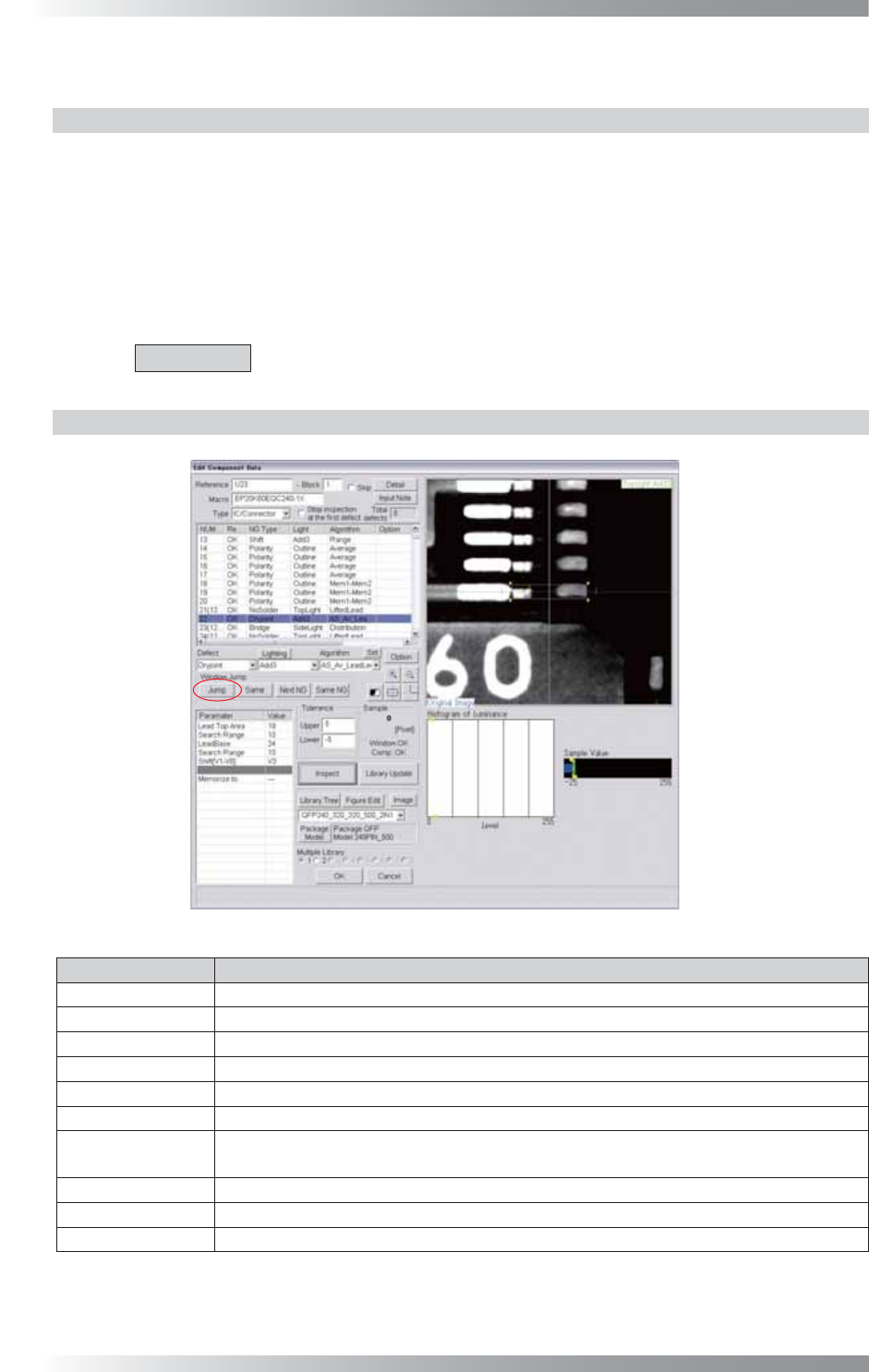
1.22.2 Parameter Setting
Figure 1-90 AS_Av_LeadLength
Parameter Description
Lighting Select arbitrarily lighting.
Algorithm Select AS_Av_LeadLength.
Lead Top Area
The inspection window size of lead end area (=yellow dotted line).
Search Range
Default is 10. Enter bigger value to extend search range of the lead end area.
LeadBase
The inspection window size of lead base area (=pink dotted line).
Search Range
Default is 10. Enter bigger value to extend search range of the lead base area.
Shift[V1-V8]
Enter the appropriate vector. Any value from V1 to V8 is available.
Select the vector according to the Memorize to fi eld of the Adjust window.
Memorize to -
Upper, Lower
Enter 5 in Upper fi eld and -5 in Lower fi eld.
Sample Shows distance of lead end area to lead base area.
Table 1-34 Parameter of AS_Av_LeadLength
III-75
Programming Manual
Part III Inspection Algorithm
1.22.3 Setting Procedure
Step1: Set search range for the lead end area. After changing parameter of Search Range below
Lead Top Area, press Inspect. Make sure that lead end area is surrounded by yellow
dotted line automatically or not.
Step2: Set inspection window size for lead end area. After changing parameter of Lead Top Area,
press Inspect. Adjust the size of the yellow dotted window.
Step3: Set search range for the lead base area. After changing parameter of Search Range below
LeadBase, press Inspect. Make sure that lead base area is surrounded by pink dotted line
automatically or not.
Step4: Set inspection window size for lead base area. After changing parameter of LeadBase,
press Inspect. Adjust the size of the pink dotted window.
Step5: Enter 5 in Upper fi eld and -5 into Lower fi eld.
NOTE
Sample value is distance of lead end area to lead base area.
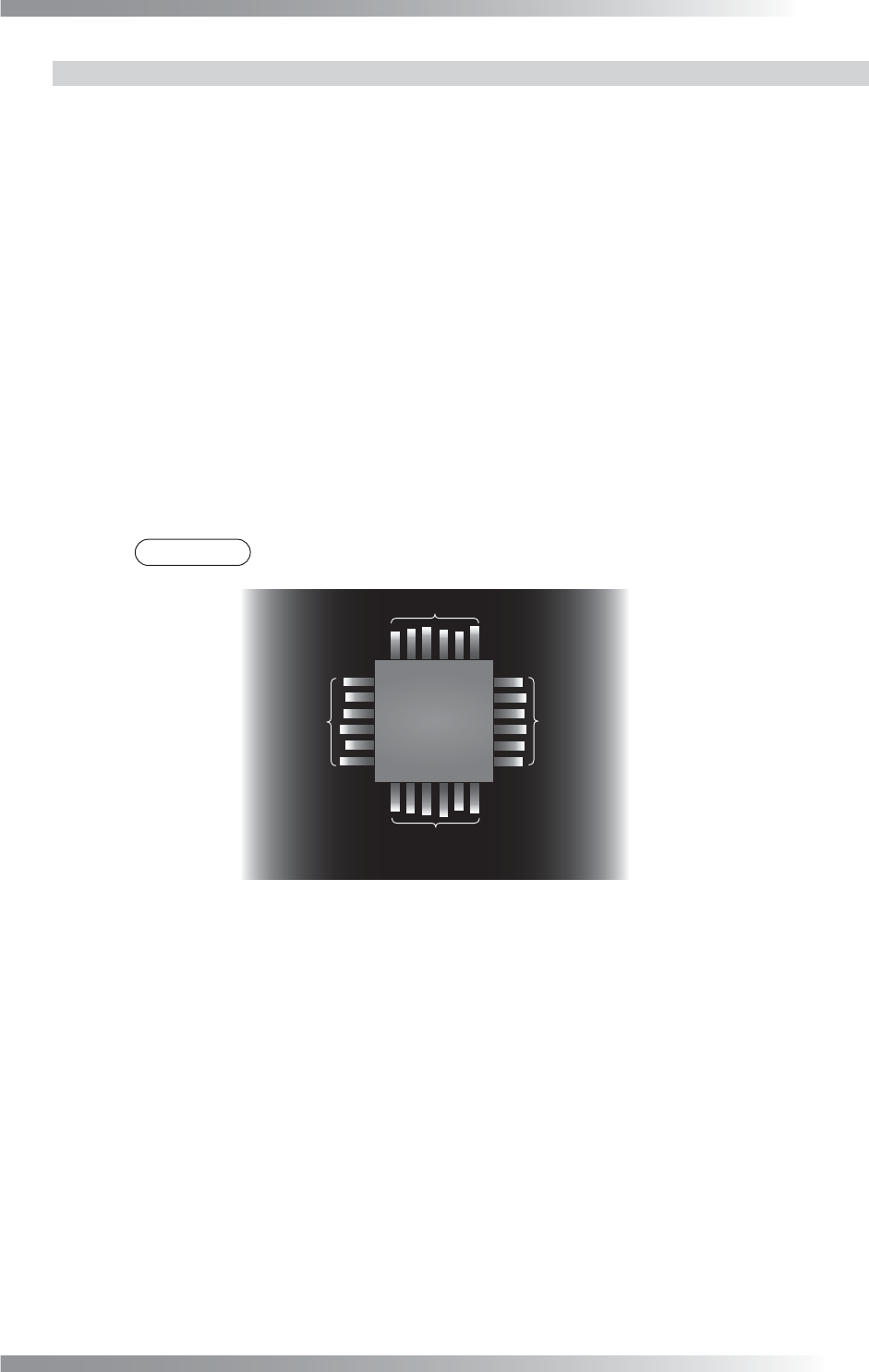
㻭㼢㼑㼞㼍㼓㼑
㻭㼢㼑㼞㼍㼓㼑
㻭㼢㼑㼞㼍㼓㼑
㻭㼢㼑㼞㼍㼓㼑
Average value for leads length
in the same side of the body
- Selected lead length
Figure 1-91 Lifted Lead Inspection by AS_Av_LeadLength
Step6: Enter the appropriate vector into the Shift fi eld. Any value from V1 to V8 is available.
Select the vector according to the Memorize to fi eld of the Adjust window.
Step7: Right-click on AS_Av_LeadLength in the inspection item list and select Parameter Copy
to copy parameter to the other leads.
Step8: Press Jump and adjust inspection window size of the corner leads in each.
Step9: Press Inspect. Make sure that the inspection is completed properly.