Programming_mail.pdf - 第43页
I- 35 Programming Manual Part I Basic Operation 2.22 War ning Setting This is the function to issue the warning if the NG or false calls are detected more than the speci fi ed occurrence frequency . As the warning is issu…
I-34
Programming Manual
Part I Basic Operation
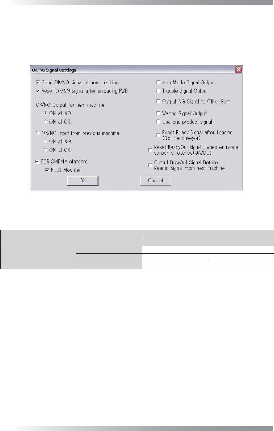
2.17 OK/NG Signals
This section describes the connection settings with upstream/downstream machines.
Press OK/NG Signals in Figure 2-1 Select System Setup.
The OK/NG Signal Settings dialog shown in Figure 2-20 appears.
For the details of each item, refer to the Signal tab in Table 2-1.
Figure 2-20 OK/NG Signal Settings
If an OK/NG In signal is output from an upstream machine, an OK/NG Out signal will be is output according
to the OK/NG In signal and an AOI’s inspection result.
Inspection Result
OK NG
OK/NG In
No Signal OK NG
OK OK NG
NG NG NG
Table 2-8 Relations between Signals from the Upstream Machine and Output Signal
2.18 IPM8540Adjust
Not available.
2.19 CPK
Not available.
2.20 Separate Conveyer
Not available.
2.21 Output Files
Not available.
I-35
Programming Manual
Part I Basic Operation
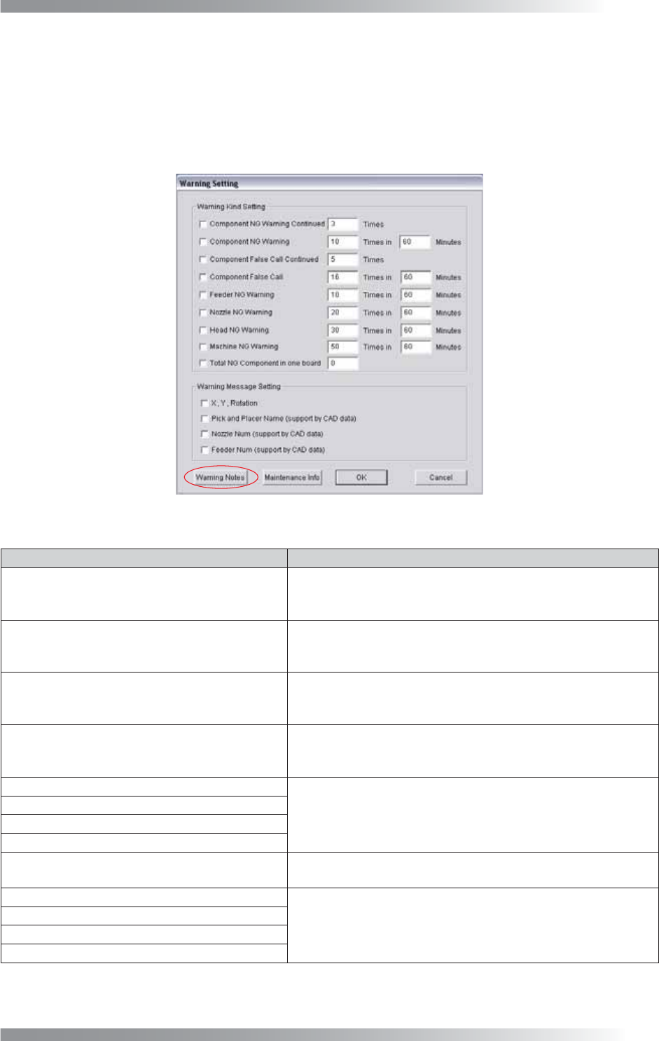
2.22 Warning Setting
This is the function to issue the warning if the NG or false calls are detected more than the specifi ed
occurrence frequency. As the warning is issued based on the frequency, errors are detected and informed
to operators although the operation is continued over the long term.
Press Warning Setting in Figure 2-1 Select System Setup. The Warning Setting dialog shown in Figure
2-21 appears. Refer to Table 2-9 Warning Kind Setting.
Figure 2-21 Warning Setting
Item Description
Component NG Warning Continued
If NG of the component in a reference are detected
continuously and the number of the continuous NG detection
reaches the specifi ed times, the warning message appears.
Component NG Warning
If the number of detected NG of a component in a reference
during the specifi ed time period (minutes) reaches to the
specifi ed time, the warning message appears.
Component False Call Continued
If false call of a component in a reference are detected
continuously and the number of the continuous false call detection
reaches the specifi ed times, the warning message appears.
Component False Call
If the number of false call of a component in a reference
during the specifi ed time period (minutes) reaches to the
specifi ed times, the warning message appears.
Feeder NG Warning
If the number of detected NG in a mounter during the
specifi ed time period (minutes) reaches to the specifi ed times,
the warning message appears.
Nozzle NG Warning
Head NG Warning
Machine NG Warning
Total NG Component in one board
If the number of NGs detected on single PCB reaches to the
set number, the warning message appears.
X, Y, Rotation
Not available.
Pick and Placer Name (support by CAD data)
Nozzle Num (support by CAD data)
Feeder Num (support by CAD data)
Table 2-9 Warning Kind Setting
I-36
Programming Manual
Part I Basic Operation
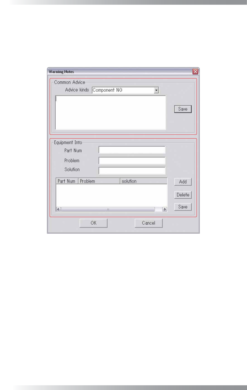
Press Warning Notes in Figure 2-21 Warning Setting.
The Warning Notes dialog shown in Figure 2-22 appears. Modify the warning message in this dialog.
In Common Advice, an advice message as to a defect type can be arranged.
Select a defect type from the Advice Kinds drop-down list and enter an advice in the text-box. Press Save.
In Equipment Info, a message for each component can be set. Press Add to add new items
Press Delete to delete items. Press Save to apply changes.
Figure 2-22 Warning Notes
2.23 Repeatability
Not available.