Programming_mail.pdf - 第107页
III- 33 Programming Manual Part III Inspection Algorithm 1.11.7 LandJ udgement Setting Pr ocedure Step1: Select two kinds of lightings to use LandJudgment . Press Set in the right side of Algorithm and select two lightin…
III-32
Programming Manual
Part III Inspection Algorithm
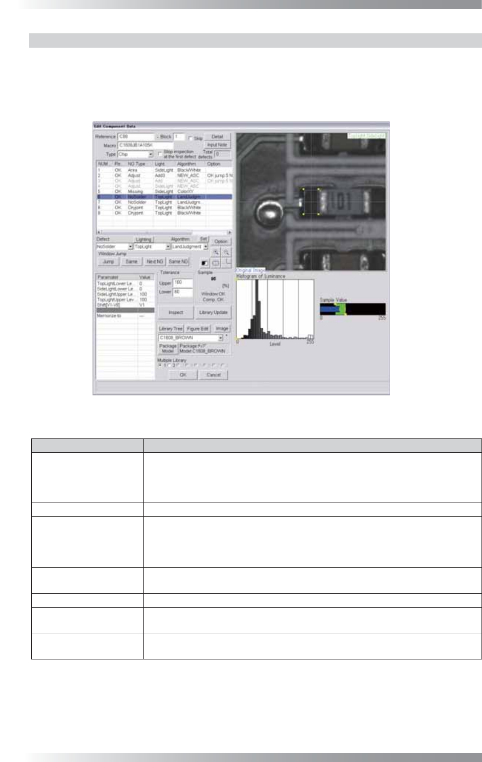
1.11.6 Algorithm LandJudgement
LandJudgement is the algorithm to perform Black/White with two lightings.
Specify the brightness level for each lighting. The algorithm calculates the percentage of the area
where the two brightness levels overlap, and displays the percentage as Sample.
LandJudgement is suitable for solder paste inspections of chip components.
Figure 1-36 LandJudgement
Parameter Description
Lighting
The selected lighting in this fi eld does not infl uence the inspection result.
Select two kinds of lightings to use LandJudgment. Press Set in the right side
of Algorithm. Select two lighting in this dialog. Default setting is TopLight and
SideLight.
Algorithm Select LandJudgement.
[Lighting1]Lower Level,
[Lighting2]Lower Level,
[Lighting2]Upper Level,
[Lighting1]Upper Level
Specify brightness level in each lighting. The percentage of the area where the
specifi ed brightness levels in each two lighting overlap in the window is displayed
as Sample.
Shift[V1-V8]
Enter the appropriate vector. Any value from V1 to V8 is available.
Select the vector according to the Memorize to fi eld of the Adjust window.
Memorize to -
Upper, Lower
Set the OK range. The maximum value is 100 in Upper and minimum value is
0 in Lower.
Sample
Calculates the percentage of the area where the two brightness levels overlap,
and displays the percentage as Sample.
Table 1-14 Parameter of LandJudgement

III-33
Programming Manual
Part III Inspection Algorithm
1.11.7 LandJudgement Setting Procedure
Step1: Select two kinds of lightings to use LandJudgment.
Press Set in the right side of Algorithm and select two lightings in this dialog.
Step2: Specify the brightness level for each lighting.
NOTE
Calculates the percentage of the area where the two brightness levels overlap, and
displays the percentage as Sample.
Step3: Set the OK range. Enter values in Upper and Lower.
Step4: Enter the appropriate vector into the Shift fi eld by selecting V1 to V8 according to the vector
used in the Memorize to fi eld in the Adjust window.
Step5: Press Inspect. Make sure that the inspection is completed properly.
III-34
Programming Manual
Part III Inspection Algorithm
1.12 LiftedLead
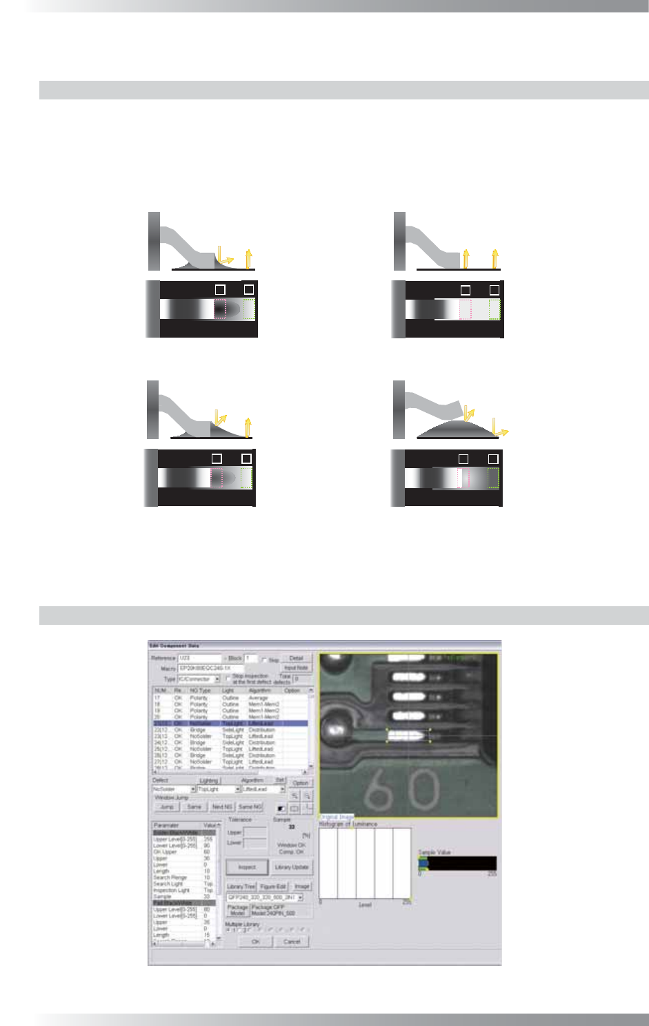
1.12.1 Inspection Overview
LiftedLead is the algorithm to calculate brightness level of solder in the lead end of IC components
and in the pad end. In ideal solder joints form, the TopLight displays lower brightness level in pad lead
area and higher brightness level in pad end area. LiftedLead is suitable for solder inspection of IC
components. For some solder shapes, brightness level in pad lead area will be high.
In this case, if the brightness level is higher in pad end area, the result will be OK.
㪈
㪉
㪈
㪉
㪈
㪉
㪈
㪉
(a) The result will be OK, if the brightness level of
(b) The result will be NG(No Solder),
(c) Inspect the brightness level of 2, if the brightness level of 1 is dubious value.
1(Lead end) is lower. 2(Pad end) does not inspect.
The result will be OK, if the brightness level of 2 is higher.
The result will be NG(lifted lead), if the brightness level of 2 is lower.
if the brightness level of 1 is lower.
Figure 1-37 Inspection of LiftedLead
1.12.2 Parameter Setting
Figure 1-38 LiftedLead