Programming_mail.pdf - 第122页
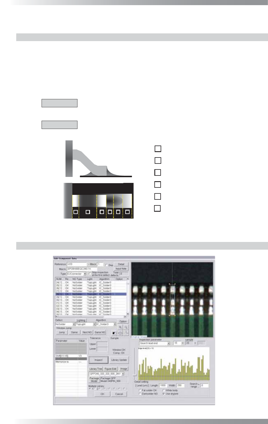
III- 48 Programming Manual Part III Inspection Algorithm 1.14 IC_Solder3 1.14.1 Inspection Ov er view IC_Solder3 is the algorithm to inspect the lead length, shift, bend, solder conditions, and lifted lead in only one in…

III-47
Programming Manual
Part III Inspection Algorithm
Step15: If changing a number of leads, press Detail shown in Figure 1-55. The dialog shown in
Figure 1-56 appears.
Figure 1-55 Detail
Figure 1-56 Number of Electrodes
Step16: Enter the number of leads in Number of Electrodes and press OK.
Step17: Enter the appropriate vector into the Shift fi eld. Any value from V1 to V8 is available.
Select the vector according to the Memorize to fi eld of the Adjust window.
Step18: Press Inspect. Make sure that the inspection is completed properly.
III-48
Programming Manual
Part III Inspection Algorithm
1.14 IC_Solder3
1.14.1 Inspection Overview
IC_Solder3 is the algorithm to inspect the lead length, shift, bend, solder conditions, and lifted lead
in only one inspection window with high accuracy.
Operability has been improved from the conventional IC_Solder2 algorithm and now lead bend can
be inspected.
It automatically locates inspection points (lead end, lead base, pad end) of an IC component.
The algorithm inspects a lead length, lead shift, lead bend, solder, copper and lifted lead in order.
CAUTION
If lead length or lead shift inspection is NG, all the following inspections, solder,
copper and lifted lead inspections are skipped.
CAUTION
IC_Solder3 is not available for two lighting system machine. It is also not valid in
combination with Part III 1.22 AS_Av_LeadLength.
㪈
㪉
㪊
㪋
㪌
㪍
㪈
㪉
㪊
㪋
㪌
㪍
Lead Base Area
Gull Wing Area
Lead End Area
Pad Lead Area
Pad Center Area
Pad End Area
Figure 1-57 Inspection of IC_Solder3
1.14.2 Parameter Setting
Figure 1-58 IC_Solder3
III-49
Programming Manual
Part III Inspection Algorithm
Parameter Description
Lighting
The selected lighting in this fi eld does not infl uence to the inspection result.
Algorithm Select IC_Solder3.
Shift[V1-V8]
Enter the appropriate vector. Any value from V1 to V8 is available. Select the vector
according to the Memorize to fi eld of the Adjust window.
Memorize to -
Table 1-23 Parameter 1 of IC_Solder3
Parameter Description
Inspection parameter
Select inspection parameter from the drop-down list to set. Refer to Part III 1.14.3
Setting Procedure.
Length Enter measured value in lead length.
Width Enter measured value in lead width.
Search range
Search range for edge between lead end area and pad lead area.
Fat solder OK
Judges heavy solder amount as OK.
Dark solder NG
Judges small solder amount as NG.
White body
It is useful to search component body which is brighter than lead base (e.g.,
Connectors).
Use dryjoint
Detects dryjoint.
Table 1-24 Parameter 2 of IC_Solder3
NOTE
When Inspect is pressed, a colored circle appears in the left side of the radio button
according to the inspection result. Red refers NG and white refers skip inspection.
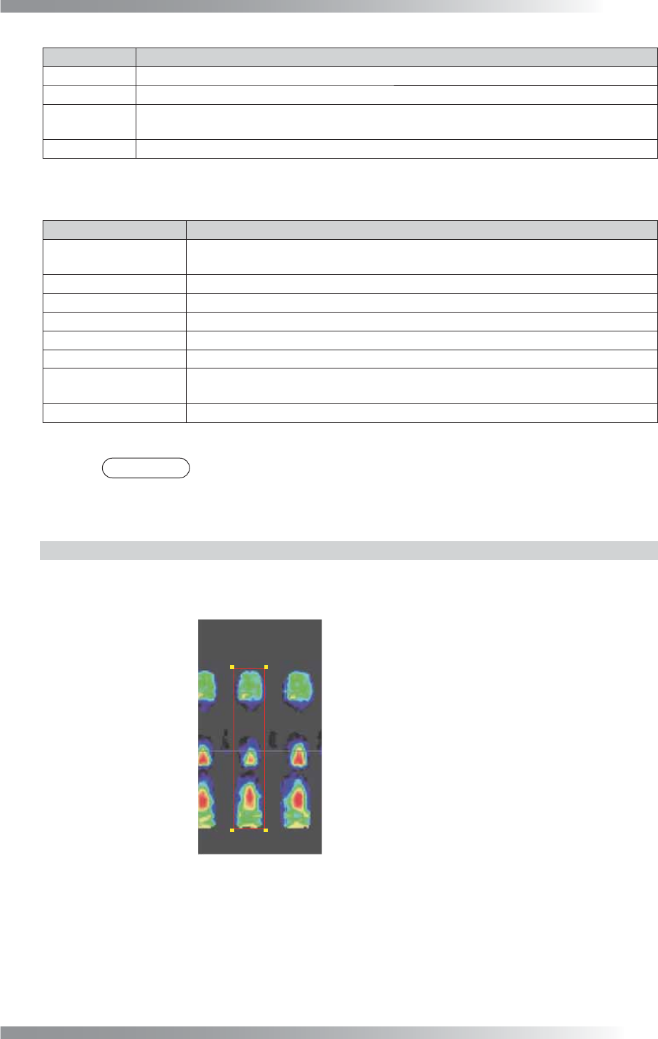
1.14.3 Setting Procedure
Step1: Adjust the size of the inspection window to surround the lead base to pad end. Window
width should be same as pad width.
Lead Base Area
Gull Wing Area
Lead End Area
Pad Lead Area
Pad Center Area
Pad End Area
Body of IC Component
Figure 1-59 Inspection Window of IC_Solder3