Programming_mail.pdf - 第103页
III- 29 Programming Manual Part III Inspection Algorithm 1.11.3 Setting Procedur e Step1: Select TopLignt from the Lighting drop-down list. Step2: Adjust the Black/White window position to surround the solder fi llet. Ste…
III-28
Programming Manual
Part III Inspection Algorithm
1.11 Black/White
1.11.1 Inspection Overview
Black/White is the algorithm to inspect the percentage of the specifi ed brightness level in the
inspection window.
If the percentage of the specifi ed level exceeds a certain value, the result will be OK.
Black/White is suitable for solder inspection of chip components.
1.11.2 Parameter Setting
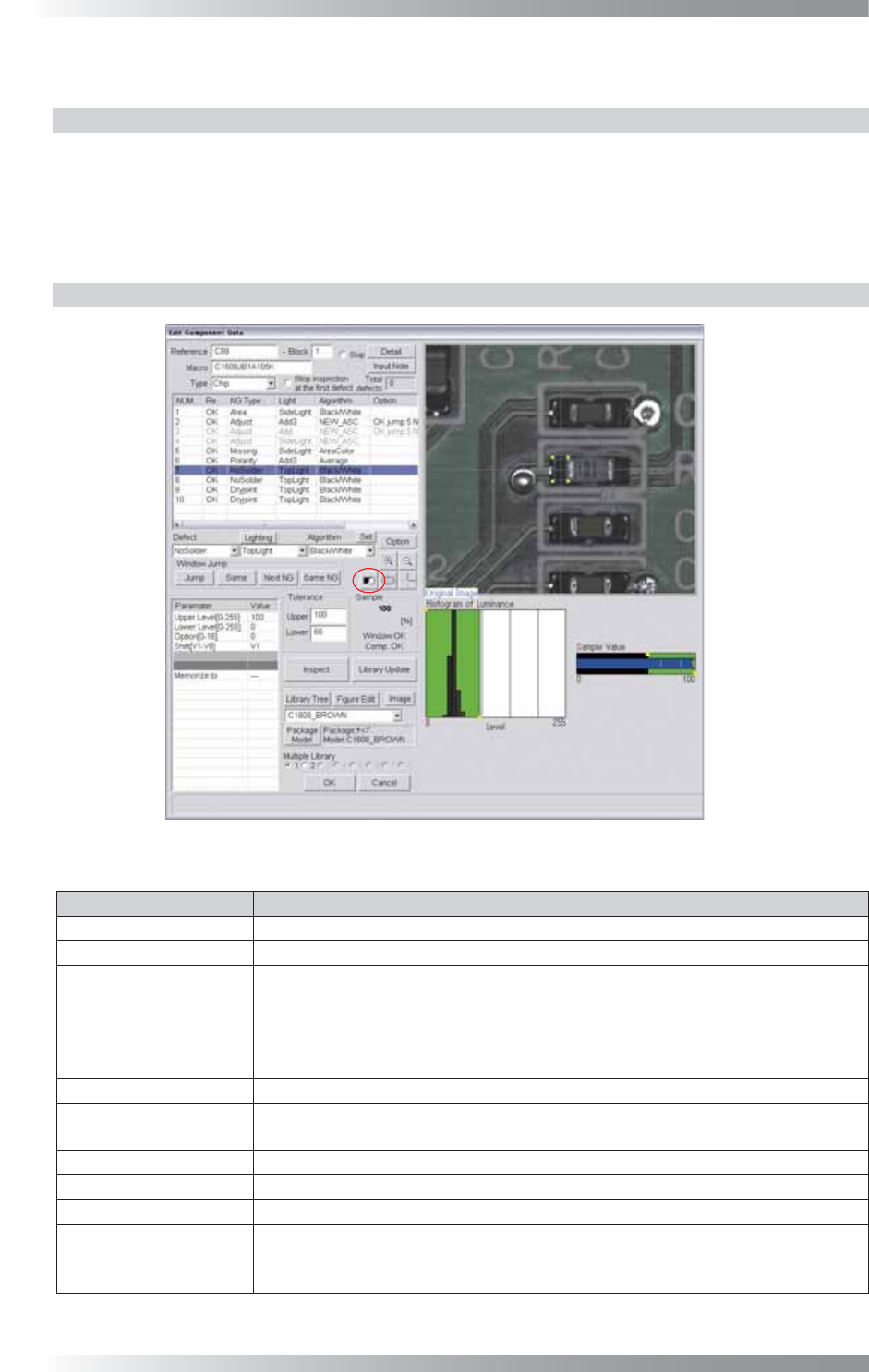
Figure 1-32 Black/White
Parameter Description
Lighting
Select TopLight to inspect solder paste.
Algorithm Select Black/White.
Upper Level[0-255],
Lower Level[0-255]
Calculates a value intermediate between OK sample value and NG sample
value. If OK sample value is smaller than NG sample value, enter intermediate
value in Upper Level fi eld and 0 in Lower Level fi eld. If NG sample value is
smaller than OK sample value, enter 255 in Upper Level fi eld and intermediate
value in Lower Level fi eld.
Option[0-16]
Enter 0.
Shift[V1-V8]
Set the OK range. The maximum value is 100 in Upper fi eld and minimum value
is 0 in Lower fi eld.
Memorize to -
Upper, Lower
Set OK range. The maximum value of Upper is 100 and minimum value of Lower is 0.
Sample
Shows the percentage of the specifi ed brightness level in the inspection window.
The graph in the lower
right side of the dialog
The Histogram of Luminance bar graph shows the number of pixels of every
bright level. Green area is the specifi ed area by Upper Level and Lower Level.
The sample Value shows upper limit and lower limit.
Table 1-12 Parameter of Black/White
III-29
Programming Manual
Part III Inspection Algorithm
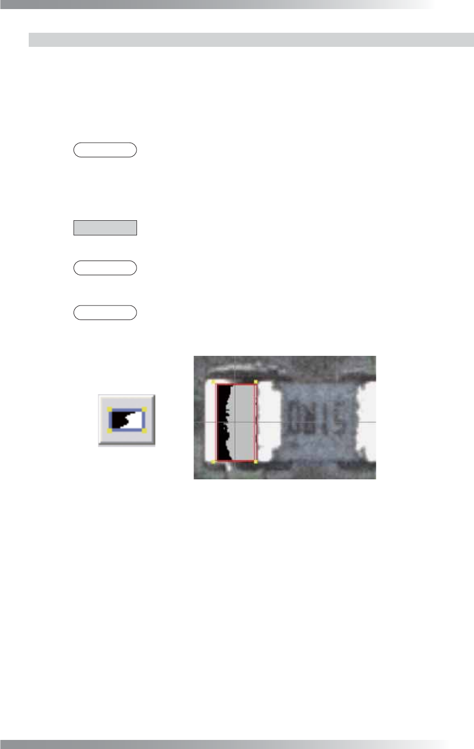
1.11.3 Setting Procedure
Step1: Select TopLignt from the Lighting drop-down list.
Step2: Adjust the Black/White window position to surround the solder fi llet.
Step3: Enter values in the Upper fi eld and the Lower fi eld.
NOTE
100 is for the Upper fi eld and 60 is for the Lower fi eld as a rough guide.
Step4: Make sure that the sample value is in the OK range. If it is out of the OK range, adjust values
in Upper Level and Lower Level.
CAUTION
Inspection windows are created at either end of the chip component after auto
deployment of chip component.
NOTE
The percentage of the specifi ed brightness level in the inspection window is
displayed as a sample value.
NOTE
Press the black-white button on the right side of Sample (refer to the red circle in
Figure 1-32). The OK area will be colored in gray.
Figure 1-33 OK Range
Step5: Enter the appropriate vector into the Shift fi eld by selecting from V1 to V8 according to the
vector used in Memorize to in the Adjust window.
Step6: Press Inspect. Make sure that the inspection is completed properly.
III-30
Programming Manual
Part III Inspection Algorithm
1.11.4 Algorithm BrightLevel
BrightLevel algorithm is available for components which brightness level are quite-variable.
Black/White algorithm calculates the percentage of the specifi ed brightness level in the inspection window.
BrightLevel algorithm inspects the brightness level which accounts for the specifi ed percentage.
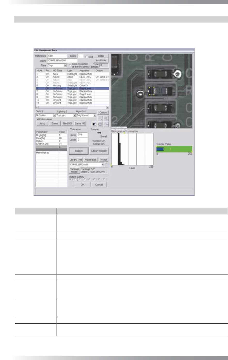
Figure 1-34 BrightLevel
Parameter Description
Lighting
Select an appropriate lighting according to the algorithm which the bright level is used.
(e.g., Select TopLight if the threshold of BrightLevel is used with Black/White for
solder inspection.)
Algorithm Select BrightLevel.
Bright[%],
Dark[%]
Enter an arbitrarily value in Bright and 0 in Dark to specify percentage of a brighter
area in an inspection window. Enter 0 in Bright and an arbitrarily value in Dark to
specify percentage of a darker area in an inspection window.
(e.g., If using Black/White in an inspection window and percentage of a bright area is
70% and percentage of a dark area is 30%, enter 70 to Bright and 0 to Dark, or enter
0 to Bright and 30 to Dark.)
Option Enter 0.
Shift[V1-V8]
Enter the appropriate vector by selecting from V1 to V8 according to the vector used
in the Memorize to fi eld in the Adjust window. Enter 0 in Shift if the threshold of
BrightLevel is used for misalignment correction.
Memorize to
Register the threshold of BrightLevel in Memorize to as M1. Enter M1 in the
appropriate parameter if other algorithms use the threshold of BrightLevel (any
values from M1 to M8 can be used to register values).
Upper, Lower
Enter 255 in Upper and 0 in Lower.
Sample
Shows a brightness level which takes a specifi ed percentage of an area if
Black/
White is used.
Table 1-13 Parameter of BrightLevel