Programming_mail.pdf - 第22页
I- 14 Programming Manual Part I Basic Operation 2 System Setup This chapter describes the detail on the system setup. Select Edit > System Setup from the menu-bar . The Select System Setup dialog shown in Figure 2-1 a…
I-13
Programming Manual
Part I Basic Operation
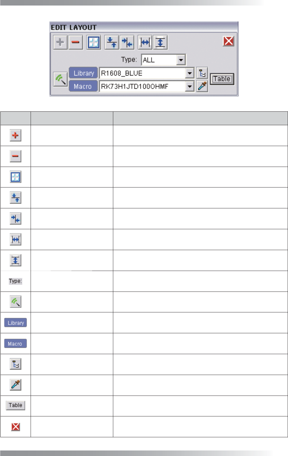
Figure 1-17 Edit Layout
Icon
Icon Name Description
Create component Creates a component data on the cross line.
Delete component Deletes selected component data.
Combine component Combines selected component data to one data.
Vertical centering Aligns selected components in parallel with the X-axis.
Horizontal centering Aligns selected components in parallel with the Y-axis.
Horizontal space equalisation Makes horizontal spaces of selected components equal.
Vertical space equalisation Makes vertical spaces of selected components equal.
Type selection Narrows down the Library selection according to the type.
Assign macro / library
Assigns the library selected in the Library selection and the macro
selected in Macro selection to components.
Library selection Select a library to be assigned in Assign macro / library.
Macro selection Select a macro to be assigned in Assign macro / library.
Library tree
Select libraries to be assigned in Assign macro / library from
Library tree.
Dropper
Applies the library/macro assigned to the selected component data
to the Library selection and Macro selection.
Correspondence table Changes the correspondence relations of libraries with macros.
Exit Exits Edit Layout.
Table 1-6 Each Item of
Edit Layout
I-14
Programming Manual
Part I Basic Operation
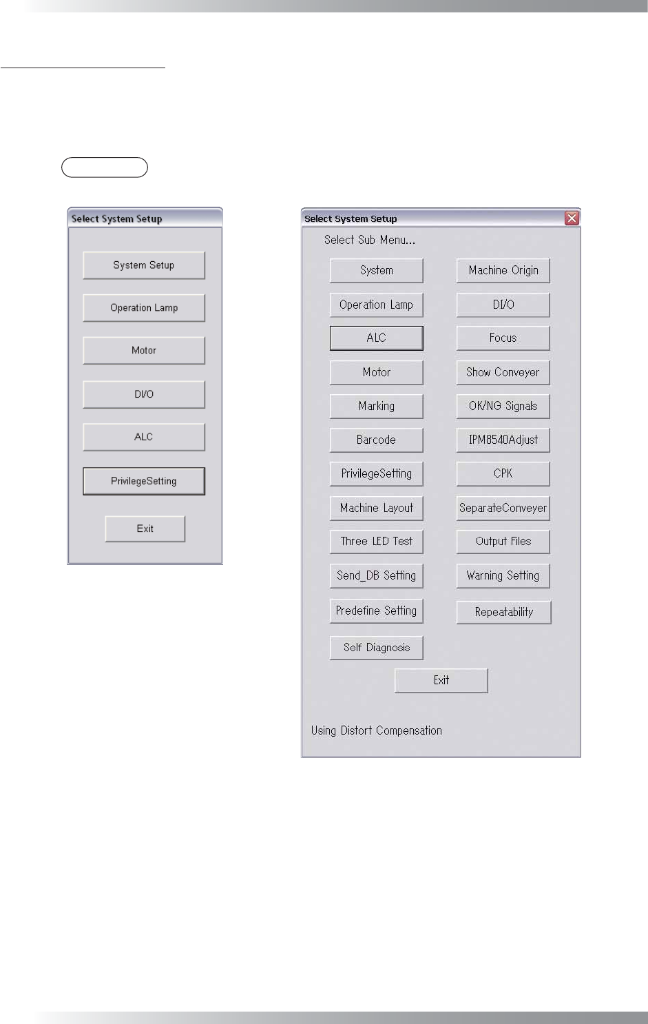
2 System Setup
This chapter describes the detail on the system setup. Select Edit > System Setup from the menu-bar.
The Select System Setup dialog shown in Figure 2-1 appears.
Each item of Select System Setup in Figure 2-1 is described as follows.
NOTE
Benchtop machines have the different dialog from inline machines.
Benchtop Machine
Inline Machine
Figure 2-1 Select System Setup
I-15
Programming Manual
Part I Basic Operation
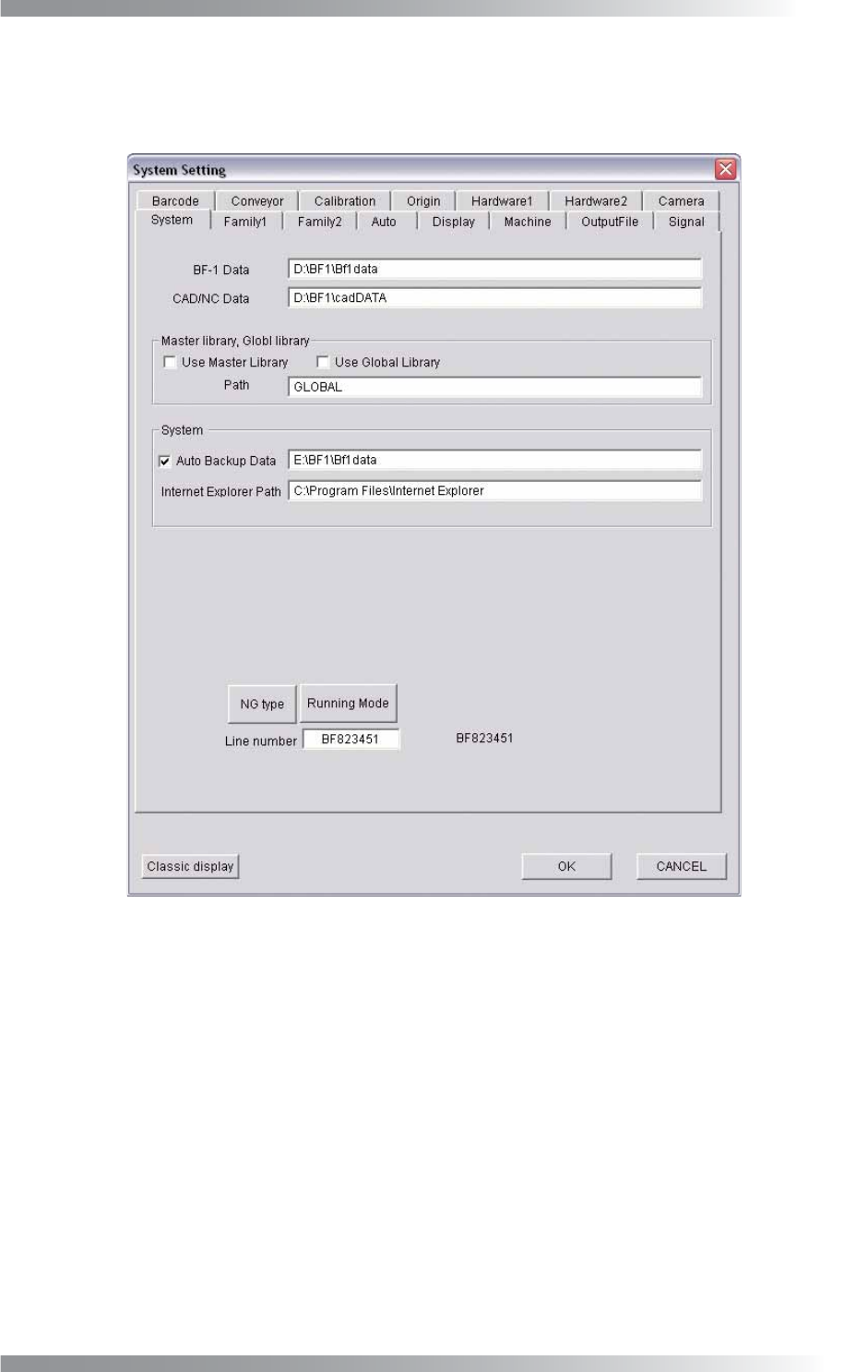
2.1 System
The destination of the fi le to save, the name of NG type or the fl ow direction of PCB can be set in System.
Press System in the Figure 2-1 Select System Setup. The System dialog shown in Figure 2-2 appears.
Figure 2-2 System