Programming_mail.pdf - 第59页
II- 15 Programming Manual Part II Inspection Data Step30: Select an algorithm from the Algorithm drop-down list. Figure of Fiducial Mark Description Square Select Gravity . Circle Select New_Circle . T able 1-9 Select Al…
II-14
Programming Manual
Part II Inspection Data
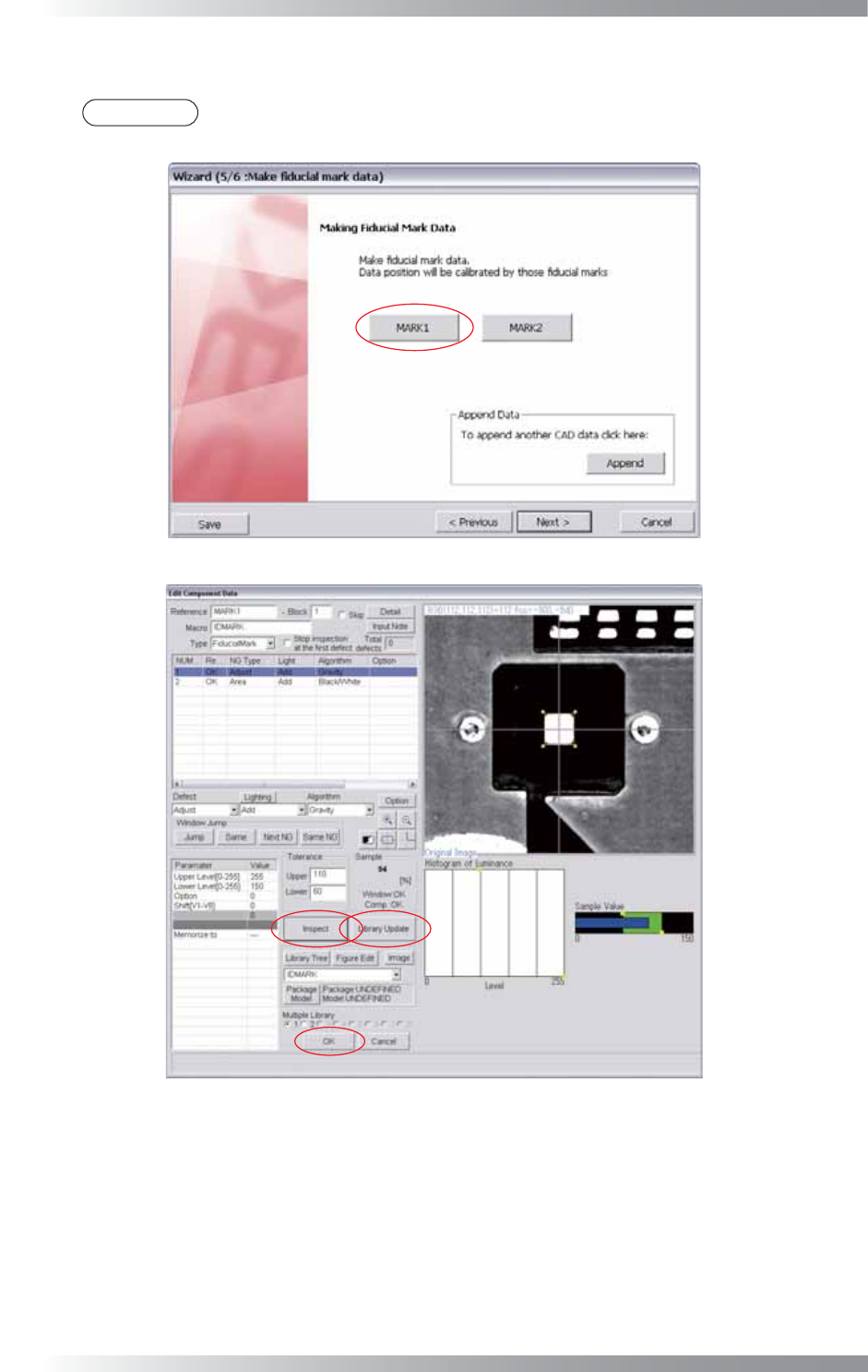
Step25: Make fi ducial mark data and press MARK1. The dialog shown in Figure 1-20 appears.
NOTE
If multiple CAD data are used, press the Append button shown in Figure 1-20 and refer to
Step3 and following steps.
Figure 1-20 Wizard 5
Figure 1-21 Fiducial Mark 1
Step26: Select Fiducial Mark from the Type drop-down list.
Step27: Right-click on the list and select Add New Window.
Step28: Select Adjust from the Defect drop-down list.
Step29: Select a lighting that a fi ducial mark is visually clear from the Lighting drop-down list.
II-15
Programming Manual
Part II Inspection Data
Step30: Select an algorithm from the Algorithm drop-down list.
Figure of Fiducial Mark Description
Square
Select
Gravity
.
Circle
Select
New_Circle
.
Table 1-9 Select Algorithm
Step31: Adjust the Adjust inspection window size to surround the fi ducial mark.
NOTE
Change Diameter to adjust inspection window size if New_Circle is used.
Step32: Enter Upper Level and Lower Level.
Brightness Level Description
Fiducial Mark > Surroundings
Enter
255
in the
Upper Level
fi eld and
150
in the
Lower Level
fi eld.
Fiducial Mark < Surroundings
Enter
150
in the
Upper Level
fi eld and
0
in the
Lower Level
fi eld.
Table 1-10 Upper Level and Lower Level setting
Step33: Right-click on Adjust and select Copy. The same parameter will be copied in 2 of NUM....
Step34: Select 2 of NUM... and select Area from the Defect drop-down list.
Step35: Adjust the size of the inspection window for Area to detect the fi ducial mark automatically.
Ideal window size is about three times bigger than the fi ducial mark size.
CAUTION
The larger inspection window can inspect the fi ducial mark even if it is out of the target
position. However, it takes longer time to inspect it and some PCB pattern might be
misjudged as a fi ducial mark.
Step36: Select Adjust and press Inspect. Pink lines crossing the center of the fi ducial mark appears if the
search is successful.
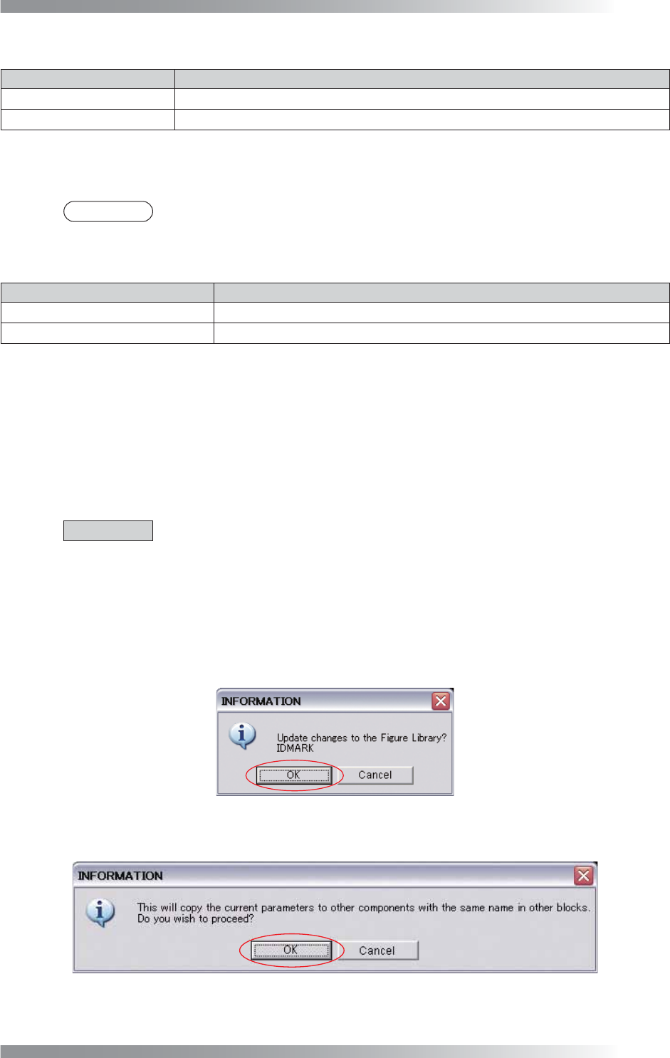
Step37: Press Update. The dialog shown in Figure 1-22 appears. Press OK.
Figure 1-22 Fiducial Mark 2
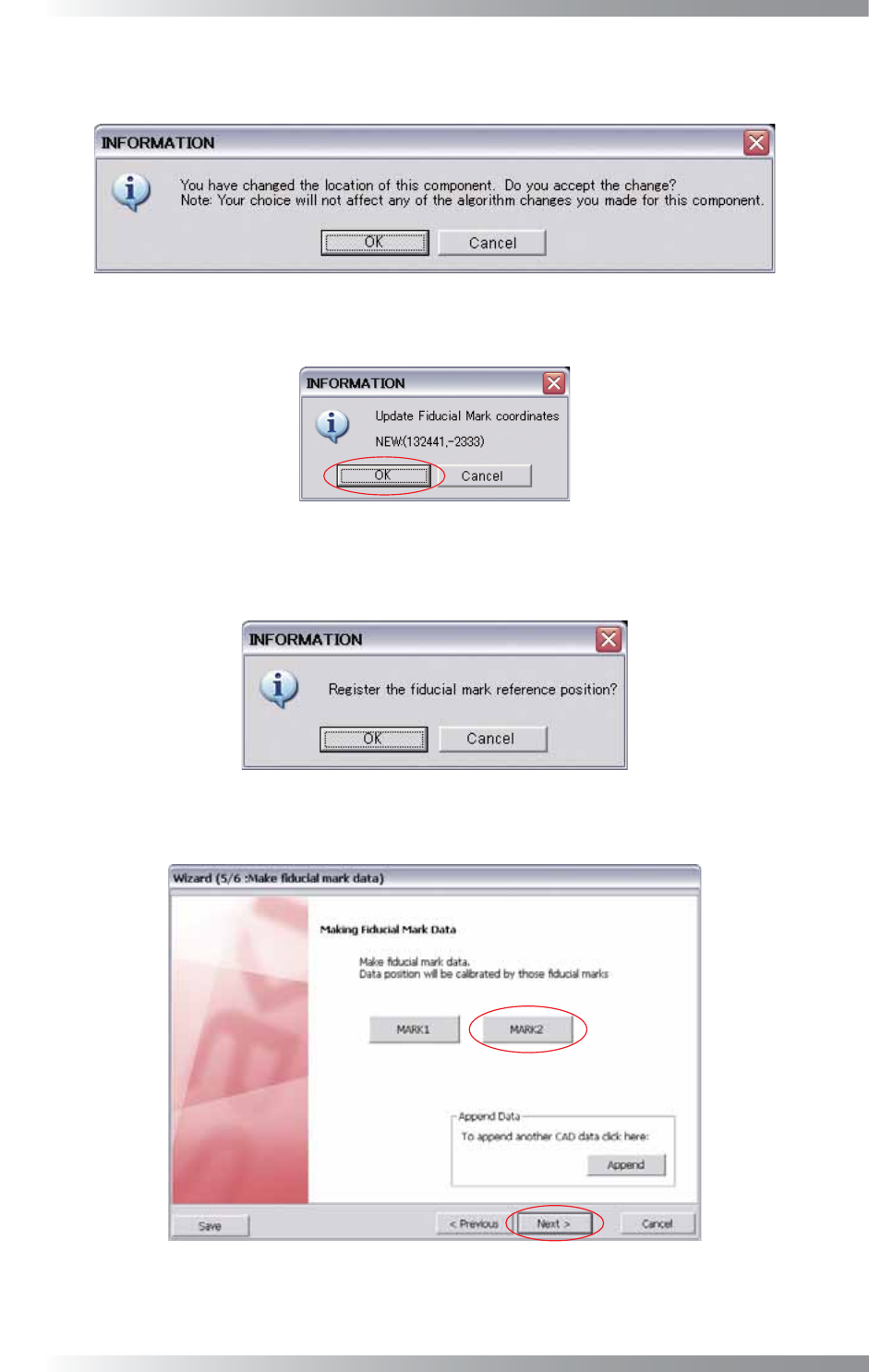
Step38: The dialog shown in Figure 1-23 appears. Press OK.
Figure 1-23 Fiducial Mark 3
II-16
Programming Manual
Part II Inspection Data
Step39: Press OK in Figure 1-21 and the dialog shown in Figure 1-24 appears. If CAD data is used, press
Cancel. If CAD data is not used, press OK.
Figure 1-24 Fiducial Mark 4
Step40: The dialog shown in Figure 1-25 appears. Press OK.
Figure 1-25 Fiducial Mark 5
Step41: The dialog shown in Figure 1-26 appears. If CAD data is used, press OK. If CAD data is not used,
press Cancel.
Figure 1-26 Fiducial Mark 6
Step42: Press MARK2 and set as well as MARK1. After all the settings are completed, press Next.
Figure 1-27 Wizard 5