Programming_mail.pdf - 第181页
IV - 17 Programming Manual Part IV Option Setting 2.5 Edit NG Inspection data of NG components can be edited. Step1: Select Edit > Edit NG from the menu-bar. The dialog shown in Figure 2-9 appears. Figure 2-9 Edit NG …
IV-16
Programming Manual
Part IV Option Setting
2.4 Delete
Components data can be deleted.
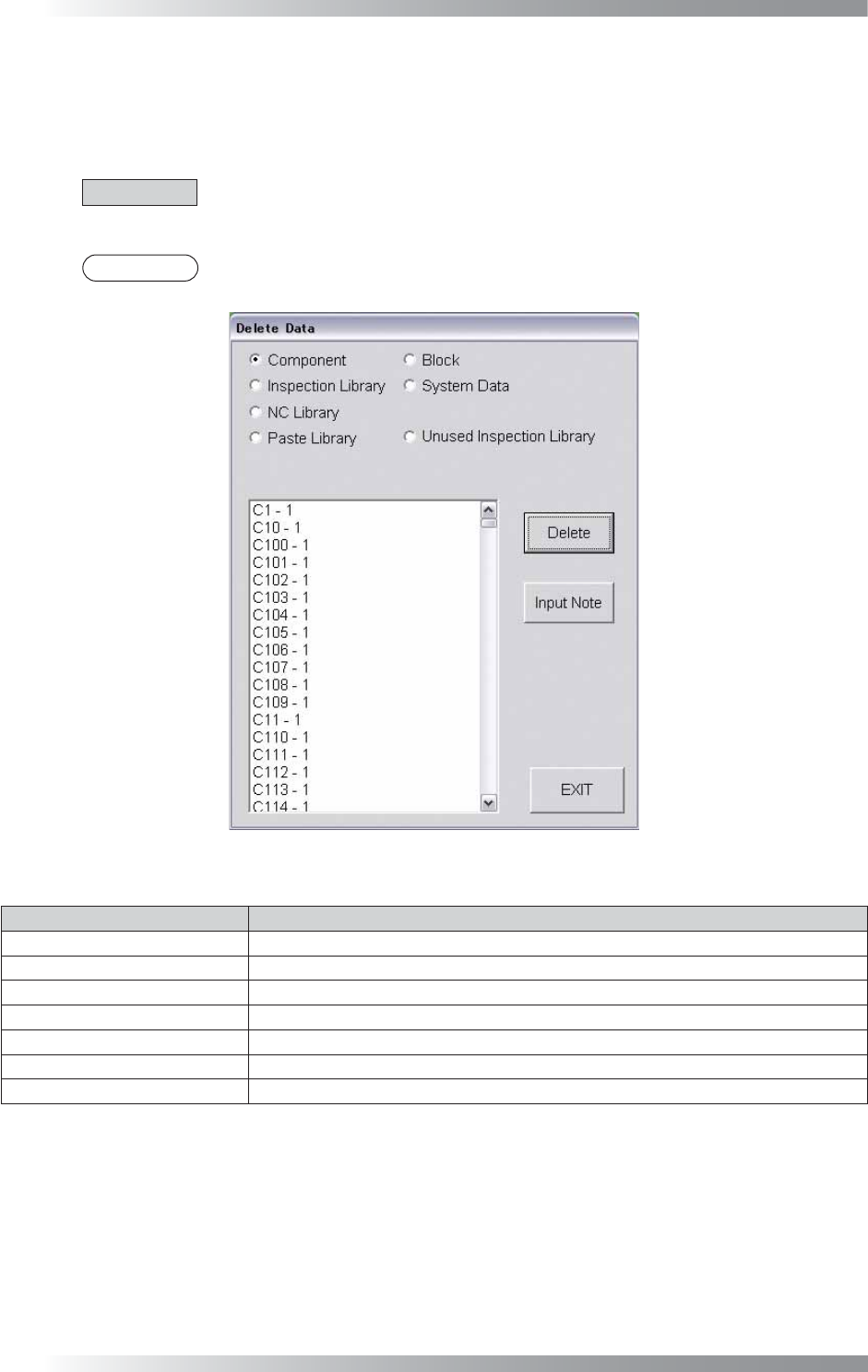
Select Edit > Delete from the menu-bar. The dialog shown in Figure 2-8 appears.
Select the component to be deleted and then press Delete.
CAUTION
To delete a library of a component whose Type is IC/Connector, delete the libraries from
Inspection Library and NC Library.
NOTE
To leave a note and a person who deleted data, press Input Note.
Figure 2-8 Delete
Item Description
Component
Displays a component data.
Inspection Library
Displays an inspection library.
NC Library Displays an NC library.
Paste Library
Displays a Paste library.
Block
Displays a sub-board data.
System Data
Displays a fi ducial mark and sub mark data.
Unused Inspection Library
Displays an unused inspection library.
Table 2-6 Delete
IV-17
Programming Manual
Part IV Option Setting
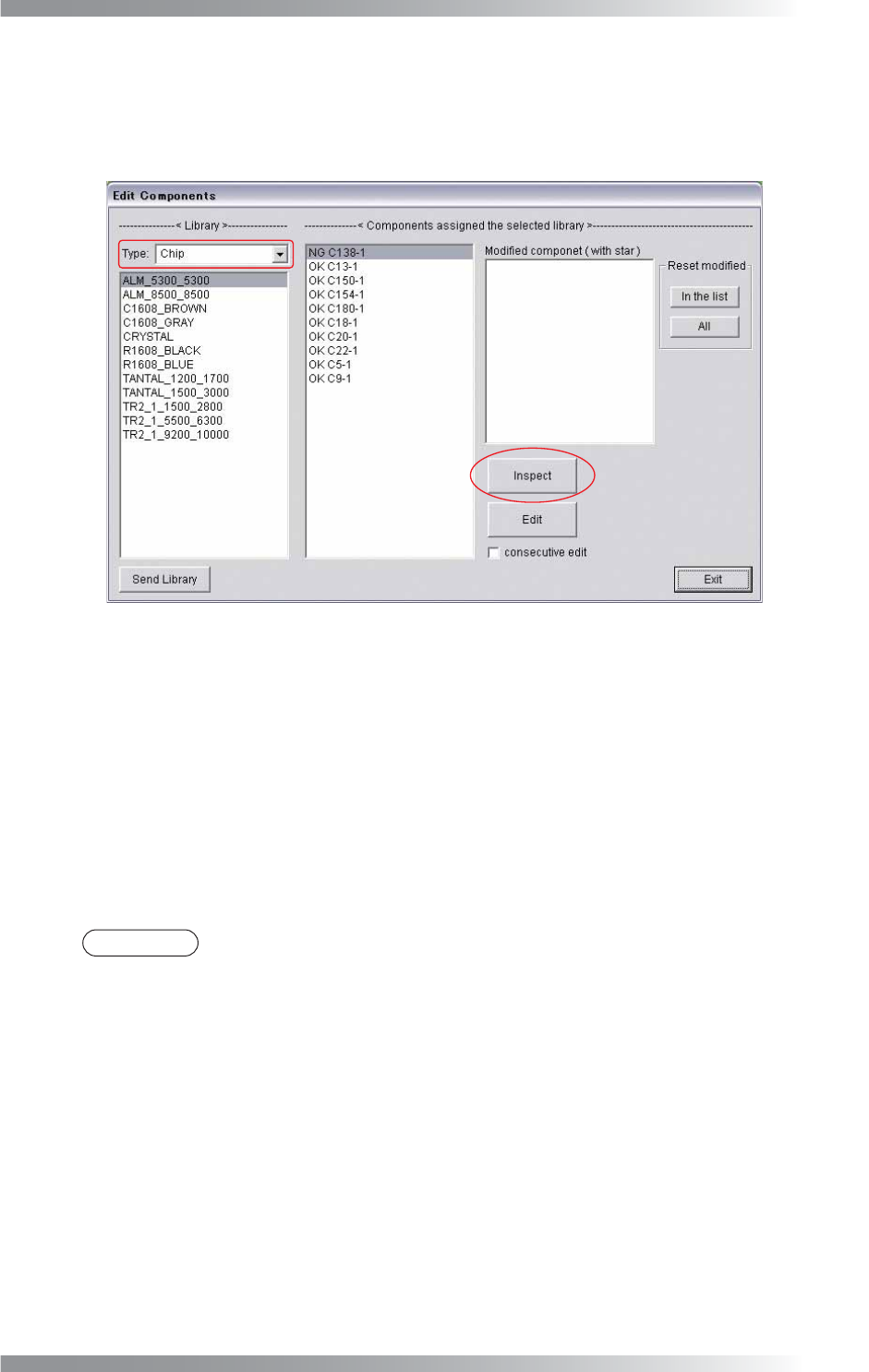
2.5 Edit NG
Inspection data of NG components can be edited.
Step1: Select Edit > Edit NG from the menu-bar. The dialog shown in Figure 2-9 appears.
Figure 2-9 Edit NG
Step2: Select the component type from the Type drop-down list.
Step3: Select the library data to be edited from the list-box.
Step4: Double-click the NG component or press Edit to display the Edit Components window.
Step5: Edit the inspection data.
Step6: Press Inspect. Make sure that NG has been changed to OK.
NOTE
In Modifi ed component, individually registered components are displayed.
To register a component individually, press OK instead of Library Update in Edit Components.
To cancel the individual registration, select a component and press In the list.
If All is pressed, all individual registration will be canceled.
IV-18
Programming Manual
Part IV Option Setting
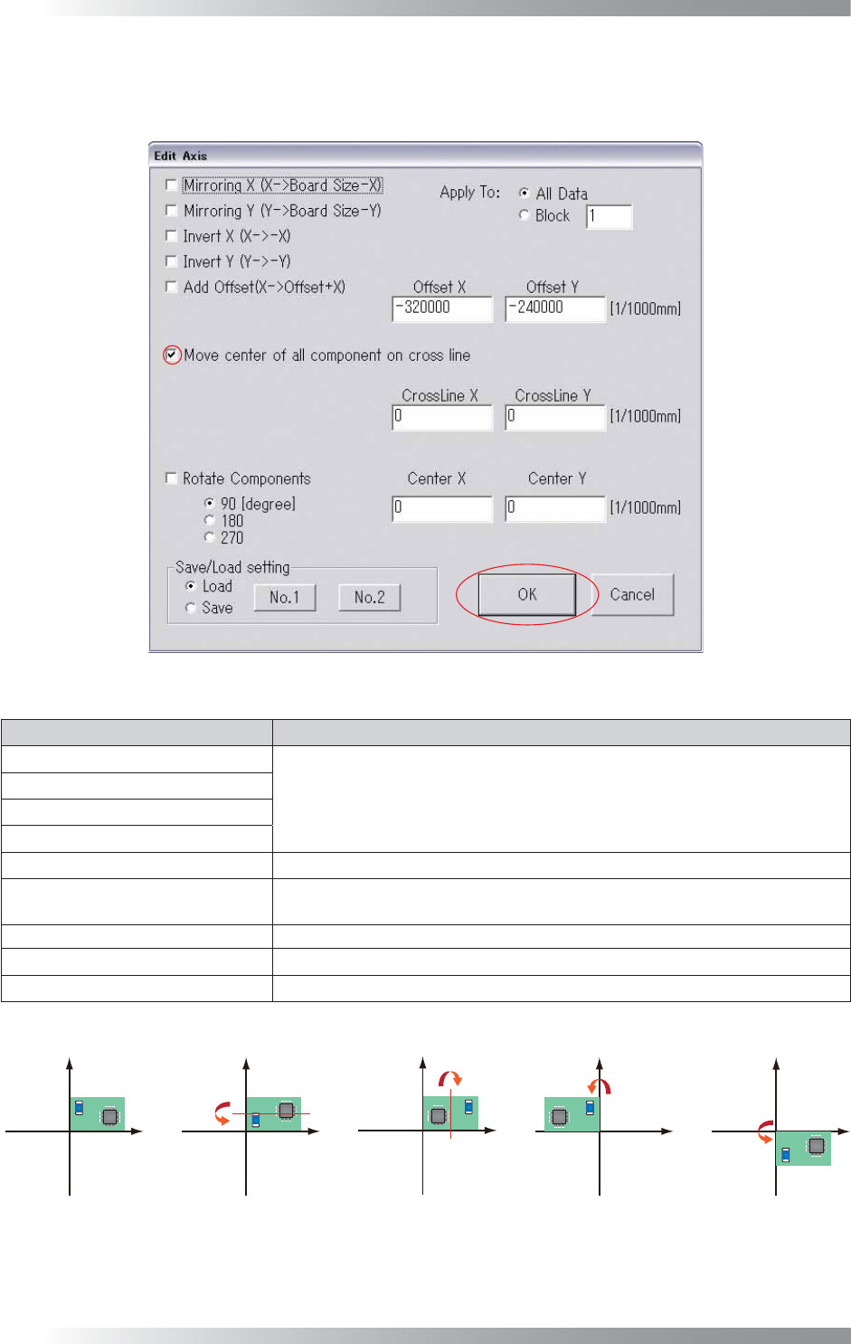
2.6 Offset
This menu can be used if an image and inspection data are misaligned.
Select Edit > Offset from the menu-bar. The dialog shown in Figure 2-10 appears.
Figure 2-10 Offset
Item Description
Mirroring X (X→Board Size-X)
Refer to Figure 2-11.
Mirroring Y (Y→Board Size-Y)
Invert X (X→-X)
Invert Y (Y→-Y)
Add Offset (X→Offset+X) Moves an inspection data by a specifi ed offset value.
Move center of all component on
cross line
Aligns the center of an inspection data to the intersection of a white cross line.
Rotate Components Rotates an inspection data by a specifi ed degree.
All Data Moves all sub board data when data exists.
Block Moves a specifi ed sub board data.
Table 2-7 Offset
(b) Mirroring X
;ĺ%RDUG6L]H;
(c) Mirroring Y
<ĺ%RDUG6L]H<
G,QYHUW;
;ĺ;
H,QYHUW<
<ĺ<
D1RUPDO
Figure 2-11 Offset