Programming_mail.pdf - 第184页
IV - 20 Programming Manual Part IV Option Setting 3 Mak e Inspection Da ta on BF-Editor The scanned image can be transferred from AOI machine to the BF-Editor . The inspection data can be made from the transferred image …
IV-19
Programming Manual
Part IV Option Setting
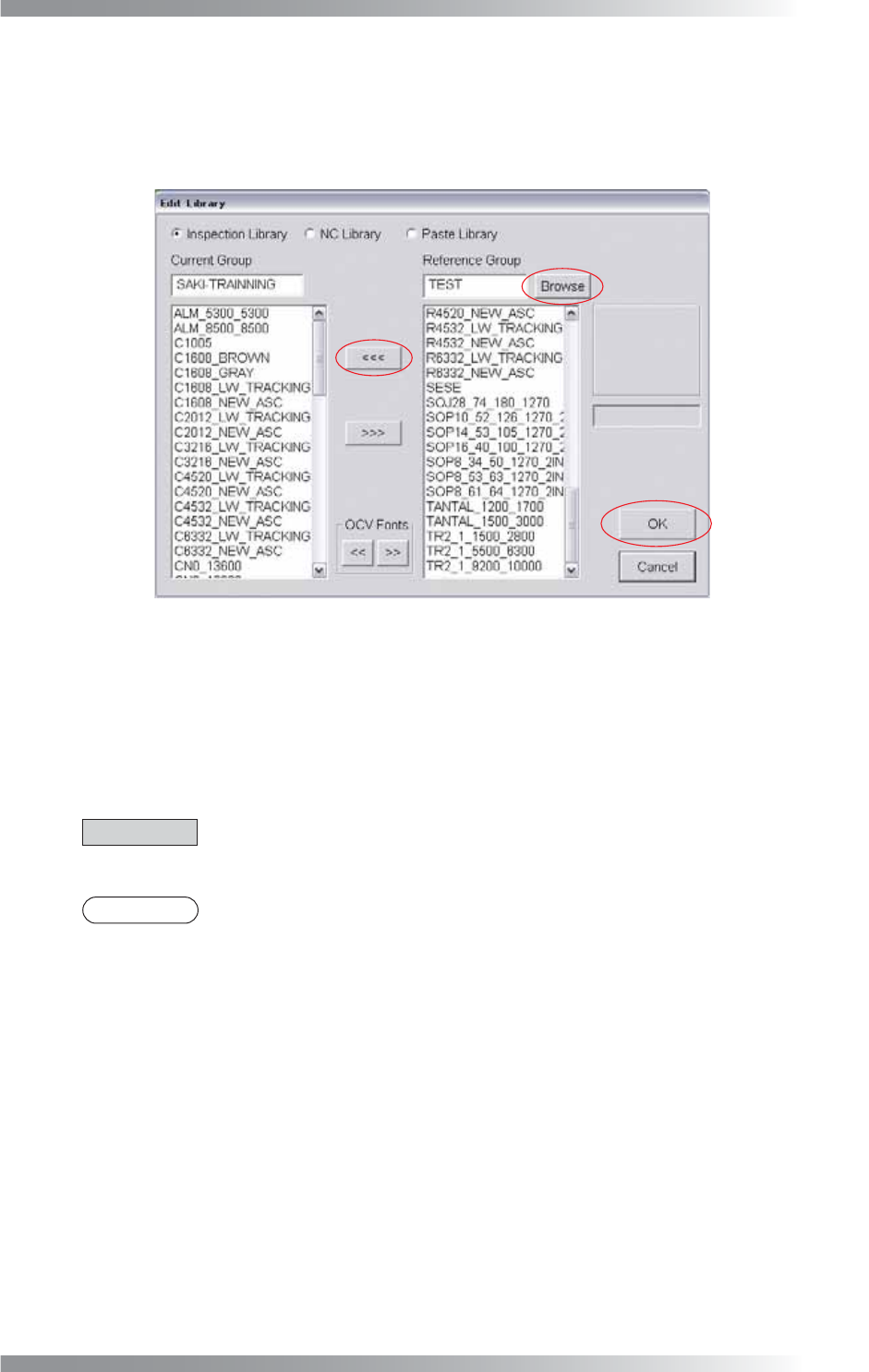
2.7 Edit Library
An inspection library can be copied to another data group.
Step1: Select Edit > Edit Library from the menu-bar. The dialog shown in Figure 2-11 appears.
Figure 2-12 Edit Library
Step2: Press Browse and select a data group.
Step3: Select a library in the Reference Group list-box and press <<<.
Step4: Press OK.
CAUTION
If copying a library of a component and the component Type is IC/Connector, copy the
libraries of Inspection Library and NC Library.
NOTE
The font registered by the OCV algorithm can be copied by pressing << or >> in OCV Fonts.
IV-20
Programming Manual
Part IV Option Setting
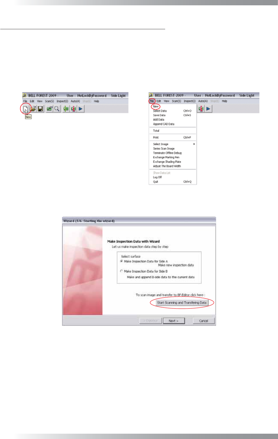
3 Make Inspection Data on BF-Editor
The scanned image can be transferred from AOI machine to the BF-Editor. The inspection data can be
made from the transferred image in BF-Editor.
3.1 Transfer Data to BF-Editor
Step1: Press New button on the tool-bar or select File > New from the menu-bar on the AOI machine.
Figure 3-1 New
Step2: Press Start Scanning and Transferring Data.
Figure 3-2 Wizard 1
IV-21
Programming Manual
Part IV Option Setting
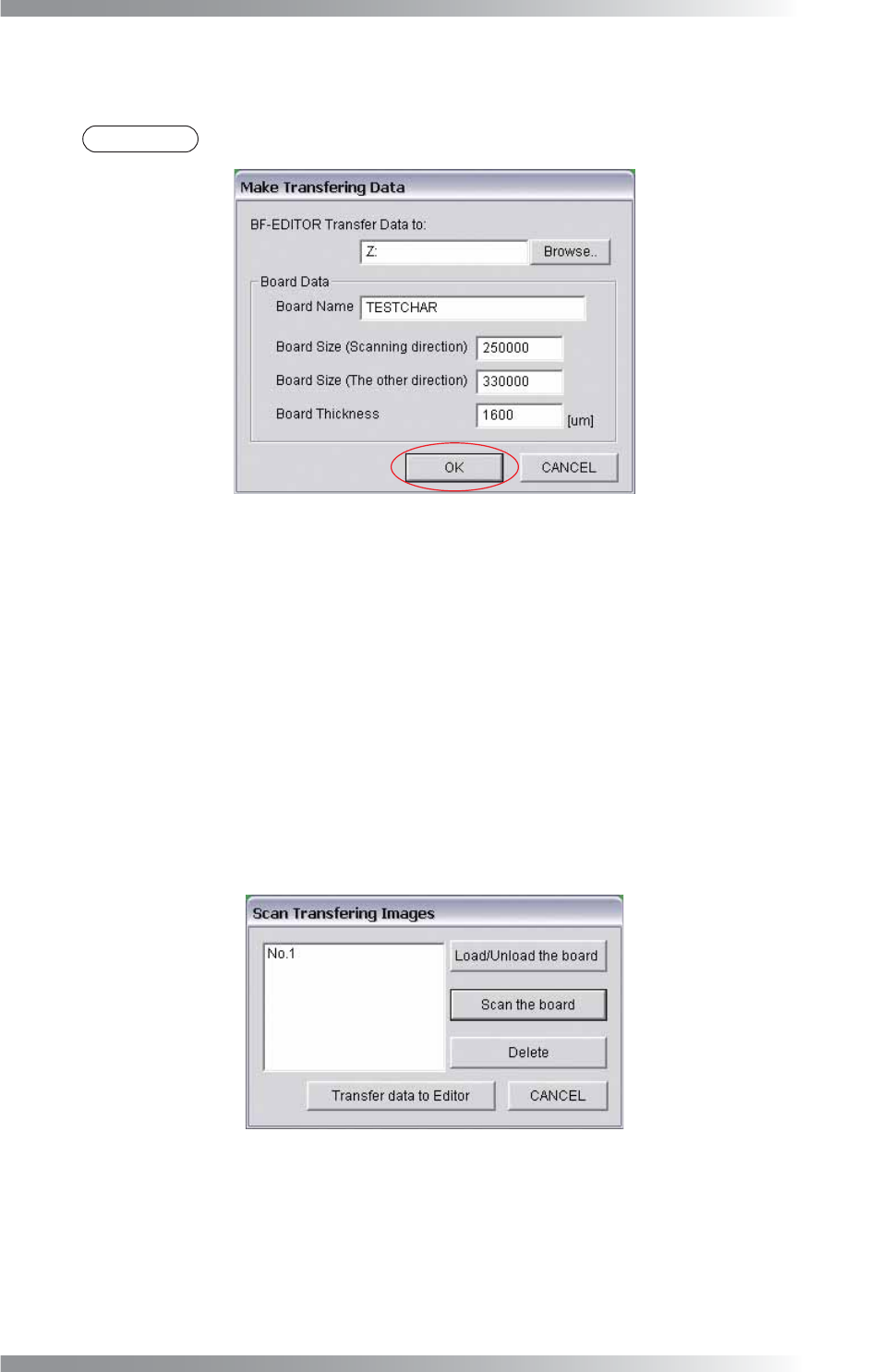
Step3: Make sure that the correct destination is entered in BF-EDITOR Transfer Data to.
Enter Board Name, Board Size and Board Thickness. Press OK.
NOTE
The destination to save the transfer data was set during the installation of BF-Editor.
Figure 3-3 Make Transferring Data
Step4: Scan the PCB. Procedures differ between benchtop machines and inline machines.
In case of benchtop machines
Set the PCB in the machine and press Scan the board. After scanning the PCB, the dialog shown
in Figure 3-5 appears. Some comments can be added if necessary. Enter comments into the text-
box and press OK. If there is no need to add a comment, press OK.
In case of inline machines
Adjust the conveyor rail width and set the PCB on the conveyor rail. Press Load / Unload the
board. After setting the PCB to the machine, press Scan the board. To unload the board, press
Load / Unload the board.
Figure 3-4 Scan Transferring Images