Programming_mail.pdf - 第211页
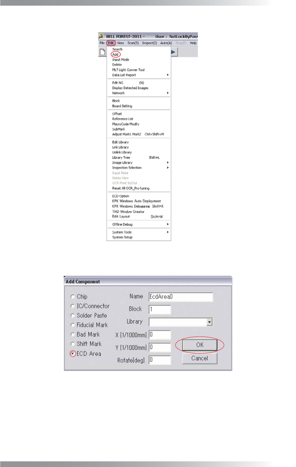
V- 21 Programming Manual Part V Other Function Step4: Select Edit > Add from the menu-bar. Figure 2-6 Add Step5: Check ECD Area and press OK . Figure 2-7 ECD Area
V-20
Programming Manual
Part V Other Function
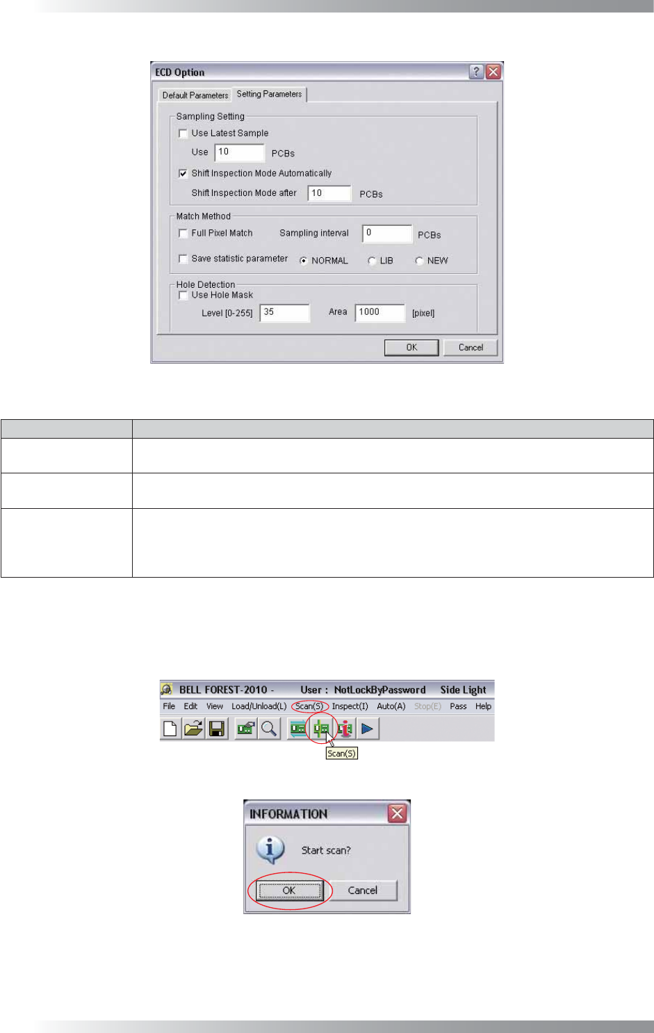
Figure 2-3 Parameter Setting
Item Description
Use Latest Sample
Latest OK image is used as template image.
Specify the number of PCBs in Use Latest.
Shift Inspection
Mode Automatically
The mode will be switched to inspection mode automatically after sampling is completed.
Default number of sampled PCB is 10.
Use Hole Mask
Excludes the through hole of PCB from inspection target.
Specify the brightness level of through hole in Level fi eld.
Specify the area of through holes in the Area fi eld. Areas darker than Level and larger than
Area will be judged as through hole and will not be inspected.
Table 2-2 Parameter Setting
Step3: Set the OK PCB. Press Scan button on the tool-bar or select Scan from the menu-bar. The dialog
shown in Figure 2-5 appears. Press OK.
Figure 2-4 Scan
Figure 2-5 Check Auto Inspection Start
V-21
Programming Manual
Part V Other Function
Step4: Select Edit > Add from the menu-bar.
Figure 2-6 Add
Step5: Check ECD Area and press OK.
Figure 2-7 ECD Area
V-22
Programming Manual
Part V Other Function
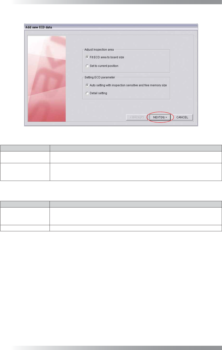
Step6: The dialog shown in Figure 2-8 appears. Check item, if necessary. Press NEXT.
Figure 2-8 Add New ECD Data
Item Description
Fit ECD area
to board size
Automatically extracts the ECD inspection window to fi t the PCB size.
Set to current position
Extracts the ECD inspection window on the white cross line displayed by left-clicking the
mouse. This item is used when changing the inspection window size or setting multiple
ECD inspection windows on the PCB.
Table 2-3 Adjust Inspection Area
Item Description
Auto setting with
inspection sensitive
and free memory size
Set a parameter automatically.
Select the inspection level from LOW, MIDDLE, HIGH depending on the inspection accuracy.
Detail setting Set a parameter manually.
Table 2-4 Setting ECD Parameter