Programming_mail.pdf - 第108页
III- 34 Programming Manual Part III Inspection Algorithm 1.12 LiftedLead 1.12.1 Inspection Ov er view LiftedLead is the algorithm to calculate brightness level of solder in the lead end of IC components and in the pad en…

III-33
Programming Manual
Part III Inspection Algorithm
1.11.7 LandJudgement Setting Procedure
Step1: Select two kinds of lightings to use LandJudgment.
Press Set in the right side of Algorithm and select two lightings in this dialog.
Step2: Specify the brightness level for each lighting.
NOTE
Calculates the percentage of the area where the two brightness levels overlap, and
displays the percentage as Sample.
Step3: Set the OK range. Enter values in Upper and Lower.
Step4: Enter the appropriate vector into the Shift fi eld by selecting V1 to V8 according to the vector
used in the Memorize to fi eld in the Adjust window.
Step5: Press Inspect. Make sure that the inspection is completed properly.
III-34
Programming Manual
Part III Inspection Algorithm
1.12 LiftedLead
1.12.1 Inspection Overview
LiftedLead is the algorithm to calculate brightness level of solder in the lead end of IC components
and in the pad end. In ideal solder joints form, the TopLight displays lower brightness level in pad lead
area and higher brightness level in pad end area. LiftedLead is suitable for solder inspection of IC
components. For some solder shapes, brightness level in pad lead area will be high.
In this case, if the brightness level is higher in pad end area, the result will be OK.
㪈
㪉
㪈
㪉
㪈
㪉
㪈
㪉
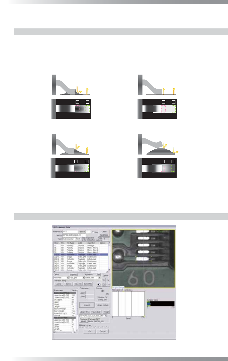
(a) The result will be OK, if the brightness level of
(b) The result will be NG(No Solder),
(c) Inspect the brightness level of 2, if the brightness level of 1 is dubious value.
1(Lead end) is lower. 2(Pad end) does not inspect.
The result will be OK, if the brightness level of 2 is higher.
The result will be NG(lifted lead), if the brightness level of 2 is lower.
if the brightness level of 1 is lower.
Figure 1-37 Inspection of LiftedLead
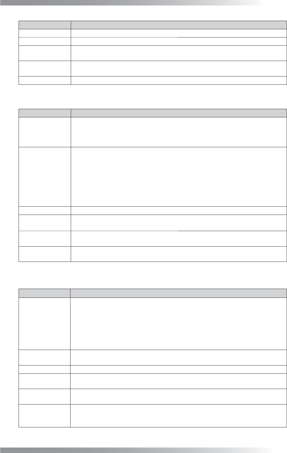
1.12.2 Parameter Setting
Figure 1-38 LiftedLead
III-35
Programming Manual
Part III Inspection Algorithm
Parameter Description
Lighting Select TopLight.
Algorithm Select LiftedLead.
Length, Width
Size of inspection window.
The value is automatically changed after the inspection window is re-sized.
Shift[V1-V8]
Enter the appropriate vector. Any value from V1 to V8 is available.
Select the vector according to the Memorize to fi eld of the Adjust window.
Memorize to -
Table 1-15 Parameter 1 of LiftedLead
Parameter Description
Upper Level[0-255],
Lower Level[0-255]
Set the brightness level of no fi llet shape. Enter 255 in Upper Level.
Lower Level is lower brightness level defi ned as NG (Default is 90).
Enter the bigger value in Lower Level if the OK sample value is higher and the result is NG.
OK Upper,
Upper,
Lower
The result is the percentage of specifi ed brightness level as NG inside inspection
window.
The result will be NG if sample value is higher than OK Upper.
The result will be OK if sample value is in the range between Upper and Lower.
If sample value is in the range between OK Upper and Upper, pad end inspection will
be done. Refer to Table 1-17 Parameter 3 of LiftedLead (Pad Black/White) to see
detail settings of solder inspection at pad end area.
Default of OK Upper is 60, Upper is 10. Enter 0 in Lower.
Length
Width of the inspection area for solder inspection (surrounded by pink dotted line).
Search Range
If enlarging this value, it expands solder auto detection area (automatically detects
solders between two pink vertical lines) at a lead end.
Search Light,
Inspection Light
Both Search Light and Inspection Light are fi xed to TopLight.
Sample
Displays the percentage of the specifi ed brightness level inside the window (solder in
the pad lead area).
Table 1-16 Parameter 2 of LiftedLead (Solder Black/White)
Parameter Description
Upper Level[0-255],
Lower Level[0-255]
If it is diffi cult to inspect solder condition only in pad lead area, the pad end inspection
will be done.
In ideal solder joints form, the pad lead area is darker and pad end area is brighter
(refer to the left side of (c) Figure 1-37 Inspection of LiftedLead). Set the brightness
level of LiftedLead. Enter smaller value in Upper Level if the OK sample value is lower
and result is NG. Upper Level is the upper brightness level specifi ed as NG. The
default is 100. Enter 0 in Lower Level.
Upper, Lower
Tolerance of the sample value. The result will be OK, If sample value is in the range
between Upper and Lower. Default of Upper is 10. Enter 0 in Lower fi eld.
Length
Width of the inspection area for lead end inspection (surrounded by green dotted line).
Search Range
If enlarging this value, it expands solder auto detection area (automatically detects
solders between two green vertical lines) at a pad end.
Search Light,
Inspection Light
Search Light is fi xed to SideLight.
Inspection Light is fi xed to TopLight.
Sample
The percentage of the specifi ed level inside the window in the pad end area.
In case the inspection is done in the pad lead area, inspection at the pad end area is
skipped and -1 will be displayed.
Table 1-17 Parameter 3 of LiftedLead (Pad Black/White)