Programming_mail.pdf - 第52页
II- 8 Programming Manual Part II Inspection Data Fixed width (each column has same length) Check Fixed width in Figure 1-8 and press Next if parameters are separated by fi xed width. Adjust column widths by dragging the b…
II-7
Programming Manual
Part II Inspection Data
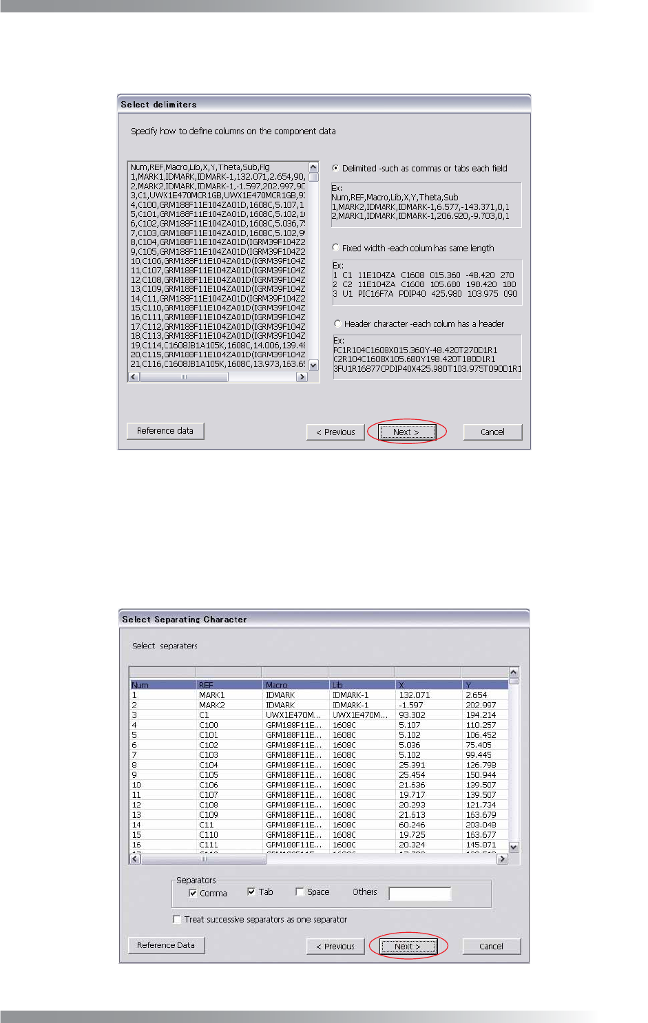
Step12: The lines specifi ed as component data in Step10 are displayed. Specify the defi nition type to
classify the data according to the type such as names or coordinates of components.
Figure 1-8 Select Delimiters
Delimited (such as commas or tabs each fi eld)
Check Delimited in Figure 1-8 and press Next if parameters are separated by comma, tab, or
space. Check the item of Separators in Figure 1-9. Each parameter is automatically separated.
Check Treat successive separators as one separator if more than one space or tab are
contained. After all the settings are completed, press Next.
Figure 1-9 Delimited (such as commas of tabs each fi eld)
II-8
Programming Manual
Part II Inspection Data
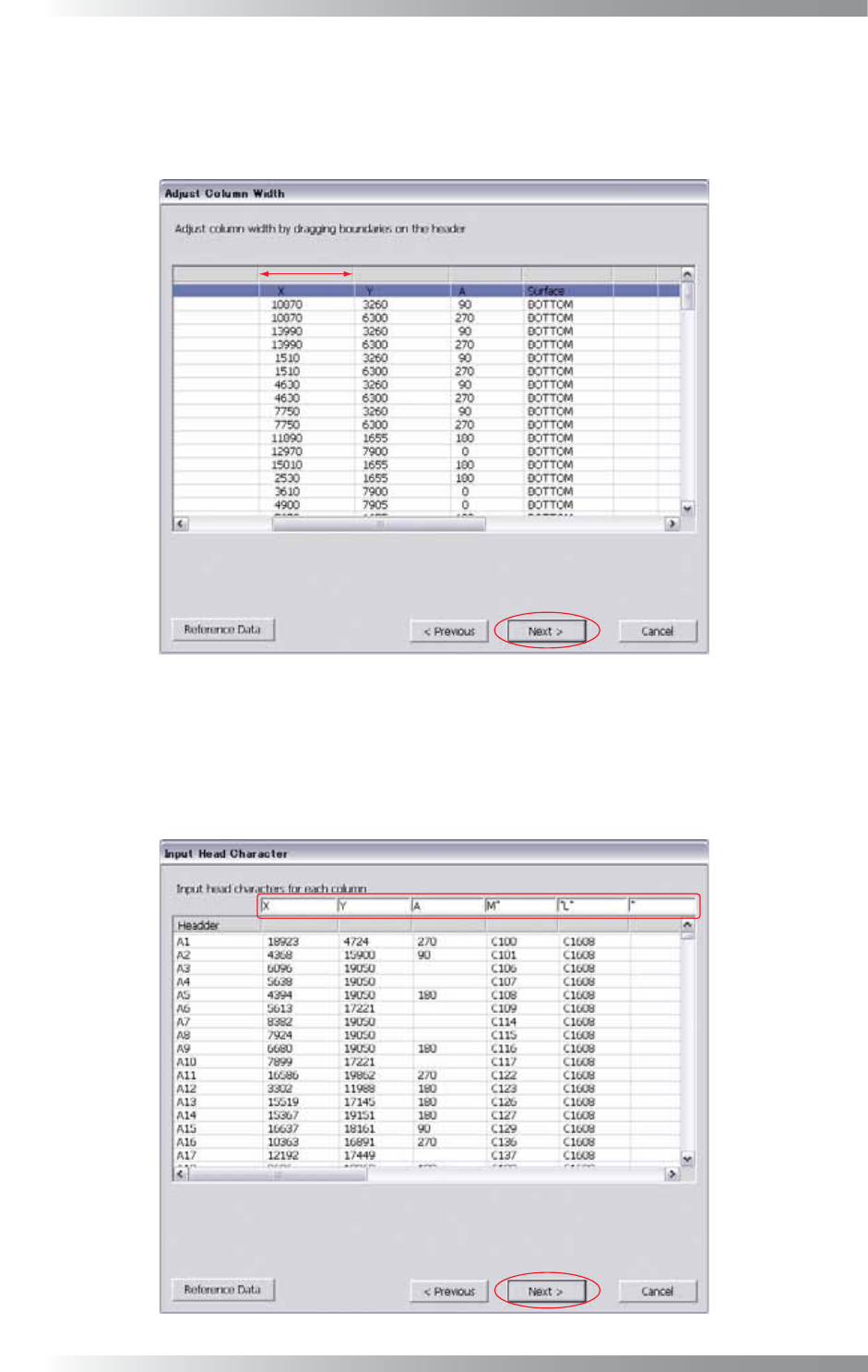
Fixed width (each column has same length)
Check Fixed width in Figure 1-8 and press Next if parameters are separated by fi xed width.
Adjust column widths by dragging the boundary of the header in Figure 1-10.
After all the settings are completed, press Next.
Figure 1-10 Fixed Width (each column has same length)
Header character (each column has a header)
Check Header character in Figure 1-8 and press Next if parameters are separated by a header
character. Enter header character of a parameter in the text-box of each column in Figure 1-11.
After all the settings are completed, press Next.
Figure 1-11 Header Character (each column has a header)
II-9
Programming Manual
Part II Inspection Data
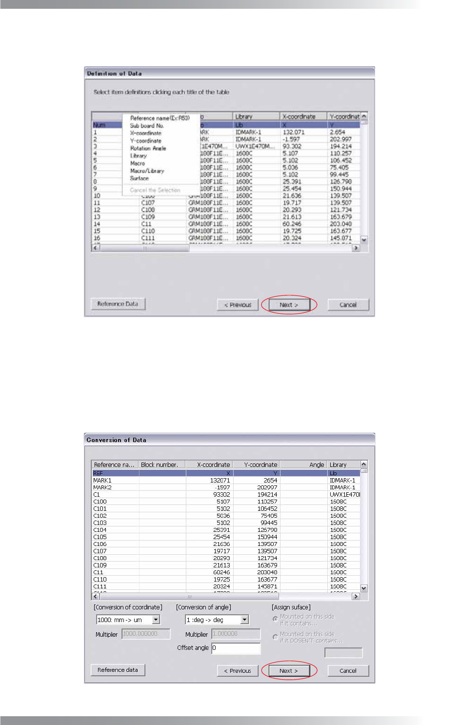
Step13: Press each column header. Parameterʼs items are displayed as shown in Figure 1-12. Select a
parameter that matches with each column. After all the settings are completed, press Next.
Figure 1-12 Defi nition of Data
Step14: Specify conversion conditions for a coordinate and an angle. Select items from the drop-down list.
Multiplier is available if Other is selected from the drop-down list. If an offset angle is entered in
the Offset angle fi eld, the specifi ed amount of offset will be added to all the component rotation.
If Surface is specifi ed in Step13, enter an appropriate parameter in the Assign surface fi eld.
After all the settings are completed, press Next.
Figure 1-13 Data Conversion