Programming_mail.pdf - 第114页
III- 40 Programming Manual Part III Inspection Algorithm 1.13.3 Setting Procedur e Step1: Adjust the size of the inspection window to surround the lead base to pad end. Window width should be the same as pad width. Lead …
III-39
Programming Manual
Part III Inspection Algorithm
Parameter Description
Lighting
The selected lighting in this fi eld does not infl uence to the inspection result.
Algorithm Select IC_Solder2.
Shift[V1-V8]
Enter the appropriate vector. Any value from V1 to V8 is available.
Select the vector according to the Memorize to fi eld of the Adjust window.
Memorize to -
Table 1-18 Parameter 1 of IC_Solder2
Parameter Description
Lead length judgement
Sets inspection parameters for lead length inspection. For details, refer to Part
III 1.13.3 Setting Procedure Step5.
Lead shift judgement
Sets inspection parameters for lead shift inspection. For details, refer to Part III
1.13.3 Setting Procedure Step6.
Table 1-19 Parameter 2 of IC_Solder2 (Lead Inspection)
Parameter Description
No solder
Sets inspection parameters for solder inspection. For details, refer to Part III
1.13.3 Setting Procedure Step7.
Copper exposure
Sets inspection parameters for copper inspection. For details, refer to Part III
1.13.3 Setting Procedure Step8.
Table 1-20 Parameter 3 of IC_Solder2 (Solder Inspection)
Parameter Description
Pad end brightness
Sets inspection parameters for lifted lead inspection. For details, refer to Part III
1.13.3 Setting Procedure Step9.
Threshold
Sets inspection parameters for lifted lead inspection. For details, refer to Part III
1.13.3 Setting Procedure Step10.
Table 1-21 Parameter 4 of IC_Solder2 (Lifted Lead Inspection)
Parameter Description
Engineer Mode
Engineer Mode enables to set detailed settings for parameters.
To set parameters with bar charts, remove the check mark.
Lead length
Enter measured value in lead length.
Lead width
Enter measured value in lead width.
Range
Search range for an edge between a lead end area and a pad lead area.
This lead Displays measured lead length.
Fat solder OK
Judges heavy solder amount as OK.
Dark solder NG
Judges small solder amount as NG.
Use dryjoint Detects dryjoint.
White body
It is useful to search a component body which is brighter than a lead base.
Table 1-22 Parameter 5 of IC_Solder2 (Detail Setting)
NOTE
Check a radio button. The corresponding histogram appears in the lower right side
of the screen.
.
NOTE
When Inspect is pressed, a colored circle may appear on the left side of the radio
button for some inspecton results. Red refers NG and white refers skip inspection.
III-40
Programming Manual
Part III Inspection Algorithm
1.13.3 Setting Procedure
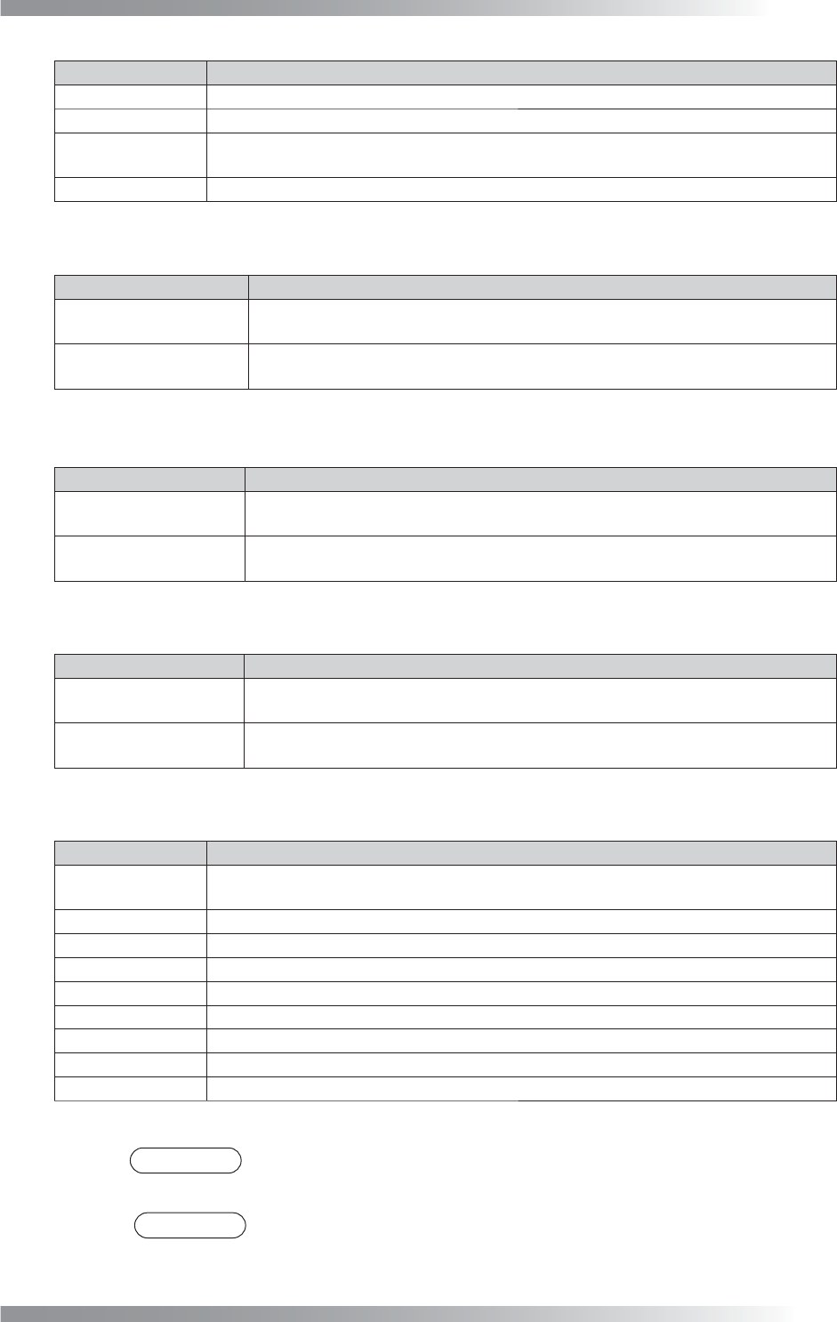
Step1: Adjust the size of the inspection window to surround the lead base to pad end. Window
width should be the same as pad width.
Lead Base Area
Gull Wing Area
Lead End Area
Pad Lead Area
Pad Center Area
Pad End Area
Body of IC Component
Figure 1-43 Inspection Window of IC_Solder2
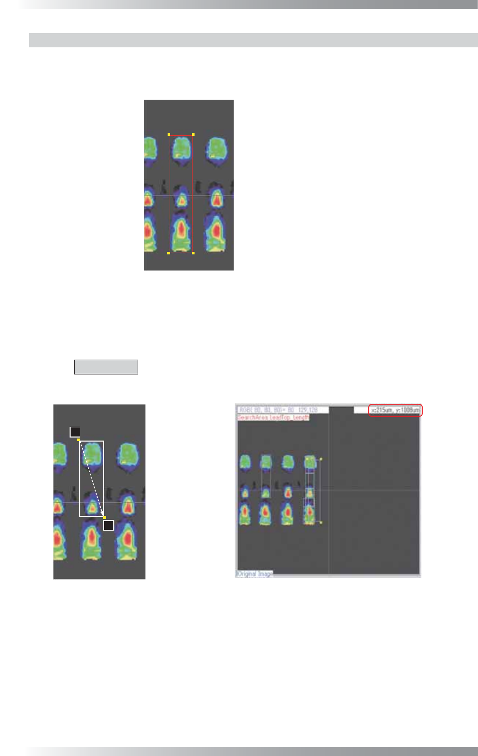
Step2: Lead length and width will be displayed in the upper right corner of the dialog if left-clicking
a lead base and dragging the pointer to opposite corner of the lead end. Enter the window
size shown in the upper right side of the dialog in Lead length and Lead width.
CAUTION
Do not measure the lead size at the lead of the selected inspection window,
otherwise the inspection window is misaligned.
㪉
㪈
Lead Base
Gull Wing Area
Lead End
Pad Lead Area
Pad Center Area
Pad End Area
Body of IC Component
Measure by another pin
Figure 1-44 Enter Lead Length and Lead Width
III-41
Programming Manual
Part III Inspection Algorithm
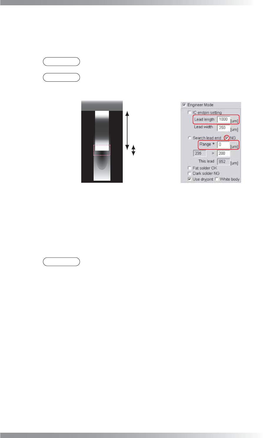
Step3: It automatically locates the edge of lead end area and pad lead area by searching the edge
of lead end and solder. Make sure that the pink dotted area includes both edge of the lead
end area and solder. If the search range is too small or too large, change the Range value
to adjust the search area size.
NOTE
NG should be always checked.
NOTE
The center of the search area is at the lead end area. Adjust the search area size
by changing the Range value.
Lead length
Range
Lead Base Area
Lead End Area
Pad Lead Area
Figure 1-45 Adjust Range
Step4: Enter the brightness level difference between the lead end and pad lead area in the lower
right side of Range. In the search area, the algorithm calculates maximum brightness level
minus minimum brightness level as the sample value (the sample value is shown in the
lower left side of Range). If the sample value is larger than the OK range, the lead end will
be located. Default is 200. Adjust parameters according to the solder condition.
NOTE
In case the lead end is covered with heavy solder, the fi llet area has brighter
brightness level and the difference between the lead end and pad lead will be
smaller. In this case, enter the search range lower than 200.