Programming_mail.pdf - 第130页
III- 56 Programming Manual Part III Inspection Algorithm Step14: In case of dry joint, the brightness level in pad center area is brighter than pad lead and pad end area. Check Use dryjoint if necessary. If Use dryjoint …
III-55
Programming Manual
Part III Inspection Algorithm
Step12: If solder volume is extremely high, the brightness level in pad area is darker. In case to
judge high-volume-solder as OK, check Fat solder OK. If Fat solder OK is checked, the
lifted lead inspection is skipped. Also after copper exposure inspection, if the average
brightness level of pad lead, pad center and pad end area is lower than 100, the result will
be OK.
Fat Solder
Figure 1-69 Fat solder OK
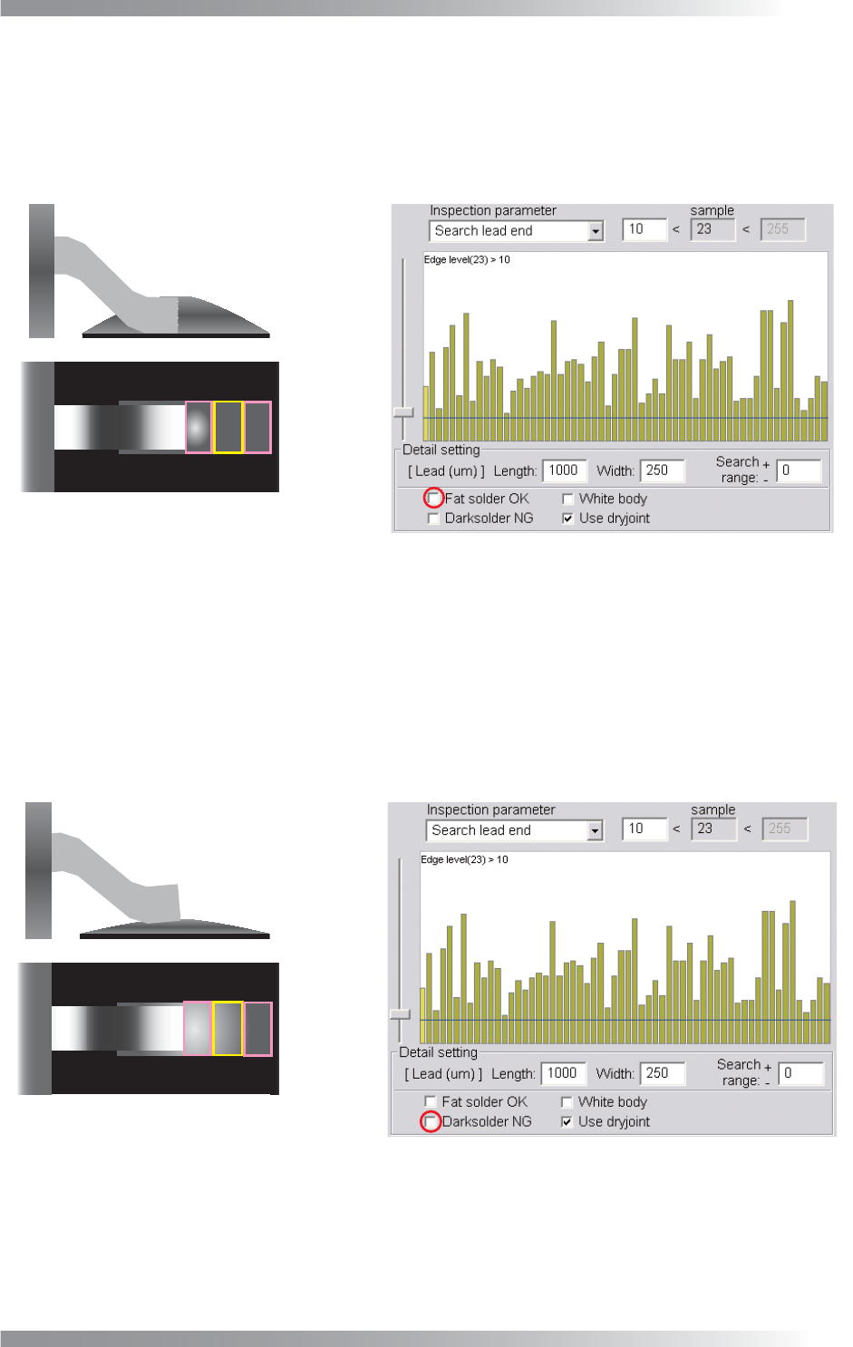
Step13: If solder volume is extremely low, the solder brightness level in pad end area is darker than
pad center area. Check Dark solder NG if necessary. The inspection is done as following
steps, lead shift, lead bend, no solder, copper exposure, and lifted lead. If Dark solder NG
is checked, lifted lead inspection will be changed. After copper exposure inspection, the
average brightness level in pad lead, pad center, and pad end area is calculated. If the
sample value is lower than 100, the result will be NG. In this case, the lifted lead inspection
will be skipped.
Dark Solder
Figure 1-70 Dark solder NG
III-56
Programming Manual
Part III Inspection Algorithm
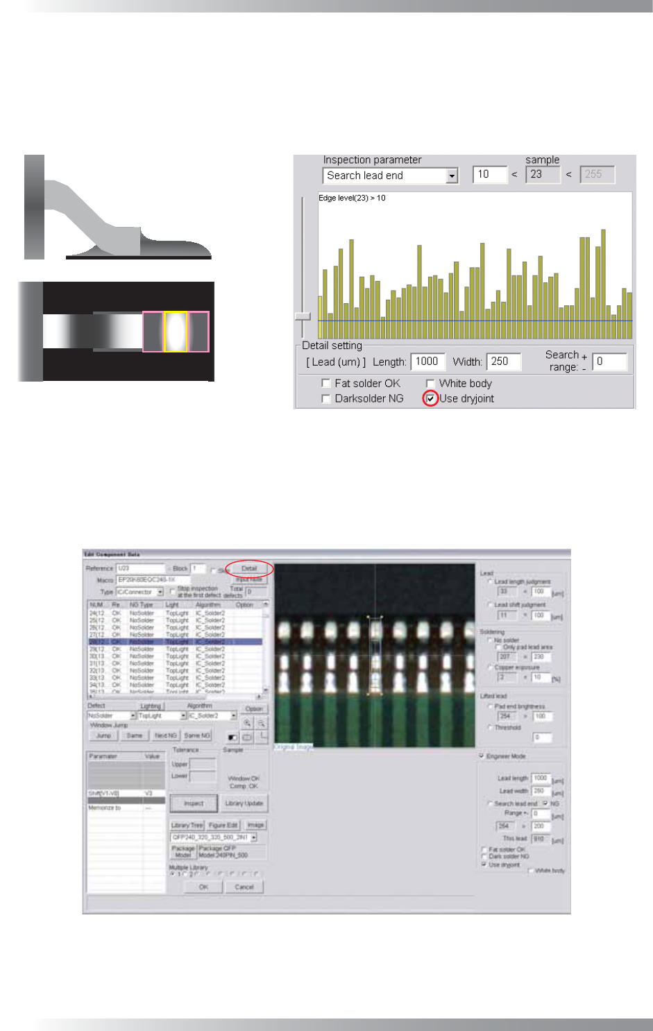
Step14: In case of dry joint, the brightness level in pad center area is brighter than pad lead and pad
end area. Check Use dryjoint if necessary. If Use dryjoint is checked and either of the
brightness level in pad end area minus pad center area or the brightness level in pad
end area minus pad lead area is failed, the result will be NG. In this case, the third
inspection, the brightness level in pad center area minus pad lead area, is skipped.
Dryjoint
Figure 1-71 Use dryjoint
Step15: Check White body in case the body is brighter than leads (e.g., Connectors).
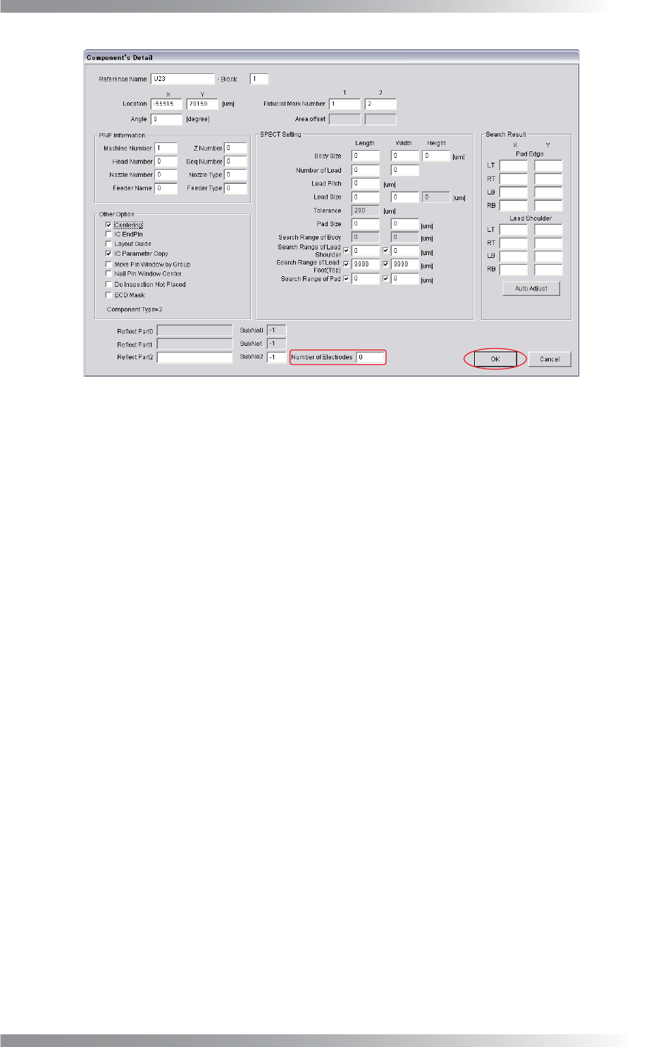
Step16: If a number of leads is changed, press Detail shown in Figure 1-72. The dialog shown in
Figure 1-73 appears.
Figure 1-72 Detail
III-57
Programming Manual
Part III Inspection Algorithm
Figure 1-73 Number of Electrodes
Step17: Enter the number of leads in Number of Electrodes and press OK.
Step18: Enter the appropriate vector into the Shift fi eld. Any value from V1 to V8 is available.
Select the vector according to the Memorize to fi eld of the Adjust window.
Step19: Press Inspect. Make sure that the inspection is completed properly.